Purpose:
The JCH-2 series static reclosing relay is used in transmission lines to cooperate with relay protection devices to achieve three-phase primary reclosing.
Features:
2.1 Static relays composed of digital integrated circuits.
2.2 Adopting a crystal oscillation time loop, the delay action time error is small and the consistency is good.
2.3 The preparation time for a reclosing is not determined by the conventional capacitor charging circuit, but by a pulse timing circuit. Therefore, the preparation time for the action is constant at 20 seconds (internally adjustable to 10 seconds, 20 seconds, 24 seconds, and adjusted to 20 seconds when the product leaves the factory), which is not affected by voltage changes and environmental temperature, improving the reliability of the action.
2.4 The outlet relay adopts a small charged current self holding type, without using mechanical time mechanism and large volume charging capacitors and resistors, so the relay has a small volume and light weight.
JCH-2 series static reclosing relay model name:
Relays are equivalent to replacing old products. The model comparison table is shown in Table 1
Note: If the export relay uses a large capacity intermediate relay, please specify it when ordering.

Working Principle:
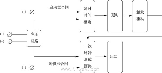
The schematic diagram is shown in Figure 1:
The relay adopts imported CMOS digital and logic integrated circuits. When the relay is connected to the DC power supply, a pulse forming circuit starts timing. After 20 seconds, the preparation light is on, and the reclosing preparation is completed, allowing reclosing. If the transmission line is in normal condition, the relay remains in the above prepared action state. When a fault occurs in the transmission line and the circuit breaker trips, the reclosing will be initiated. After a delay setting, the driving output relay will be triggered, and its current holding circuit will be maintained until the circuit breaker is closed. At the same time, a pulse forms a circuit reset. If the transmission line is experiencing a temporary fault, after the circuit breaker is successfully closed, a pulse will form a circuit to re time and the relay will be in a ready to operate state again. If there is a permanent fault in the transmission line, the reclosing will not be successful and the circuit breaker will trip for the second time. However, this period of time is much shorter than the 20 second countdown time for a pulse to form a circuit, so the relay is guaranteed not to operate.
The relay can be externally locked through the locking terminal to prevent reclosing, and the relay preparation light will not light up at this time.
Usage:
6.1 After the relay is connected to the DC power supply for 20 seconds, the indicator light is ready to light up and the relay is in normal working condition.
6.2 The delay setting of the reclosing action adopts a two digit 8421 code digital dial switch, and the formula for time setting is t=0.1 ˇÁ MN (s).
There are two sets of two digit switches on the JCH-2C type reclosing relay panel. The upper set of digital switches sets the reclosing delay time (J3), and the lower set of digital switches sets the J relay delay time (J2, J4). The time setting formula is t=0.1 ˇÁ MN (s).
Main technical parameters:
8.1 DC rated voltage: 48V, 110V, 220V.
8.2 Closing current: 0.5A, 1A, 2A, 5A.
8.3 Delay range: 0.1-9.9s, with a difference of 0.1s.
The interval time for one reclosing is 20s ˇŔ 0.05s.
8.5 Under rated conditions, at any point within the delay range, the absolute value of delay error shall not exceed (0.1%+10ms), and the absolute value of delay consistency shall not exceed (0.1%+10ms).
8.6 Power consumption shall not exceed 5W.
8.7 Dielectric Strength
The circuits of the relay and the exposed non-conductive metal and shell should be able to withstand an effective value of 2Kv, 50Hz AC voltage for 1 minute, and there should be no insulation breakdown or flashover phenomenon.
8.8 Contact breaking capacity
Under the conditions of current not exceeding 2A and voltage not exceeding 250V, the external output contact can disconnect a DC inductive load of 50W with a time constant of 5ms ˇŔ 0.75ms.
8.9 Working conditions
a) The usage location does not allow explosive media, and the surrounding media should not contain corrosive metals, gases that damage insulation, or conductive media. It is not allowed to be filled with water vapor or have serious mold presence;
b) Strong vibrations and impacts are not allowed in the usage location;
c) The usage location should have facilities to defend against rain, snow, wind, and sand;
d) The usage location does not allow an external magnetic induction intensity exceeding 1.5mT.
8.10 Electrical anti-interference relays shall comply with GB7261 and GB6261 "Electrical anti-interference tests for static relays and protective devices".
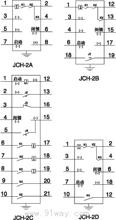
JCH-2 series static reclosing relay back wiring diagram:
Relay external dimensions and opening dimensions:
The JCH-2A relay adopts an upward protruding fixed structure, and its external dimensions and installation hole dimensions are shown in Appendix Figure 1;
The JCH-2B relay adopts an A-Ji protruding plug-in structure (code JK-3), and its external dimensions and installation hole dimensions are shown in Appendix Figure 2;
The JCH-2C relay adopts an A-Ji protruding plug-in structure (code JK-3), and its external dimensions and installation hole dimensions are shown in Appendix Figure 2;
The JCH-2D relay adopts the Xuji embedded plug-in structure (code A32K), and its external dimensions and installation hole dimensions are shown in Appendix Figure 3.
Ordering instructions:
9.1 Product model and name;
9.2 Rated voltage and closing current;
9.3 Order quantity;
9.4 If there are special requirements, please specify.

