
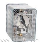
| Product nameŁş | DS-110/120Q series time relay | ||||||
| specificationŁş |  |
||||||
| CategoryŁş | low-voltage electrical apparatus -- time relay | ||||||
| PriceŁş | factory price | ||||||
| BrandŁş | |||||||
| Place of OriginŁş | China | ||||||
| Available QuantityŁş | batch | ||||||
| delivery cycleŁş | Spot goods (or inquire by telephone) | ||||||
|
|||||||
1. Application of DS-110/120Q series time relay
DS-Q series time relays (hereinafter referred to as relays) are used as auxiliary components in various protection and automatic circuits, enabling adjustable delay in the action of controlled components.
2. Structure and operating principle of DS-110/120Q series time relay
2.1 The relay adopts embedded installation, and the main body is a plug-in structure.
2.2 The main body of the DS-Q series time relay is the same as that of the DS series time relay.
2.3 The relay is a suction type electromagnetic relay with a delay mechanism.
2.4 The relay has one instantaneous conversion contact and one delayed dynamic closing contact. For DS-114, 115, 116, 124, 125, 126Q type relays, an additional delayed sliding main contact is required.
The coil of the 2.5 relay is fixed inside the U-shaped magnet. When a voltage is applied to both ends of the coil, the rotor (iron core) is sucked in and instantly makes contact
Point half closing, the dynamic breaking contact opens, and at the same time, the delay mechanism starts to move. Under the action of the tension spring of the delay mechanism, after a certain period of time (set time), the main contact of the delayed dynamic closing is closed (for DS-114, 115, 116, 124, 125, 126Q relays, the sliding main contact is closed first, and then the final dynamic closing main contact is closed after a certain period of time). The period from the moment the voltage is applied to the electromagnetic coil to the time when the main contact of the delayed closing can be adjusted by changing the position of the static contact, and indicated directly on the scale of the relay by the pointer. When the coil is powered off, the chirp and delay mechanism instantly return to their original positions under the action of the tower spring.
The internal wiring diagram of the 2.6 relay is shown in Figure 1.
The appearance and installation dimensions of the 2.7 relay are shown in Figure 2.
DS-111Q DS-121Q
DS-112Q DS-122Q
DS-113QDS-123QDS-111CQ
DS-112CQ
DS-113CQDS-114Q DS-124Q
DS-115Q DS-125Q
DS-116Q DS-126Q
Figure 1 Internal wiring diagram of DS-110 120 Q series time relay (back view)
3 Technical Requirements
3.1 The main technical data of various relays are listed in the table.
3.2 Reliable operating voltage of relays: not exceeding 70% of the rated voltage for DC relays; For AC relays, the rated voltage shall not exceed 85%.
3.3 The reliable return voltage of the relay shall not be lower than 5% of the rated voltage.
The variation in the action time of the main contact of the relay shall not exceed 3.4. ˇŻ
3.4.1 DS-111CQ, DS-11lQ, DS-12lQ, DS-114Q, and DS-124Q shall not exceed 0.06s.
3.4.2 DS-112CQ, DS-112Q, DS-122Q, DS-115Q, and DS-125Q shall not exceed 0.12s.
3.4.3 DS-113CQ, DS-113Q, DS-123Q, DS-116Q, and DS-126Q shall not exceed 0.25s.
Note: ˘Ů Action time variation refers to the difference between the maximum and minimum action times measured 10 times at the same time set point.
˘Ú The parameters specified in Articles 2, 3, and 4 are environmental temperature of+20 ˇćˇŔ 5 ˇć.
3.5 Thermal stability
3.5.1 DSŁ¬11lQˇ˘DS-112Qˇ˘DSŁ¬113Qˇ˘DS-114Qˇ˘DS-115Qˇ˘DS-116Qˇ˘DS-12lQˇ˘DS-122Qˇ˘DS-123Qˇ˘DS-124Qˇ˘DS-125Q The coil of the DS-126Q relay can withstand 110% of the rated voltage for 2 minutes, and the temperature rise of the coil does not exceed 60k.
3.5.2 The coils of DS-111CQ, DS-112CQ, and DS-113CQ relays can withstand 110% of the rated voltage for a long time.
Note: For DS-111CQ, DS-112CQ, and DS-113CQ relays, voltage should be applied to terminals 1-7 (see Figure 1).
3.6 Power consumption of relays at rated voltage
DS-111CQ, DS-112CQ, DS-113CQ type relays -12W;
DS-111Q, DS-112Q, DS-113Q, DS-114Q, DS-115Q, DS-116Q type relays -36W;
DS-12lQ, DS-122Q, DS-123Q, DS-124Q, DS-125Q, DS-126Q type relays -75VA.
When the current is not greater than lA and the voltage is not higher than 220V, in a DC circuit with an inductive load and a time constant not exceeding 0.005s, the breaking power of the contacts is 100W.
3.8 The dielectric strength between all circuits of the relay and the shell, non-metallic parts, and electrically unrelated circuits should withstand AC 50Hz, voltage 2kV, and test for 1 minute without breakdown or flashover.
At the maximum delay setting point, the relay can withstand 5000 turns on and off without mechanical damage.
Note: The number of actions per hour should not exceed 30.
3.10 The relay operates reliably within the ambient temperature range of -20 ˇć to+40 ˇć.
The weight of the 3.11 relay is approximately 2kg
4 Ordering Instructions
4.1 Name, model, and specifications of the relay.
4.2 Rated voltage of relay.
4.3 Number of relays.
HomeŁüQuality CommitmentŁüOrderingŁüPayment methodŁüproduct deliveryŁüsupportŁüDisclaimerŁüContact Us
Copyright®2011 www.91way.com Copyright.
PhoneŁş+86-21-66770508 +86-13916500500 FaxŁş+86-21-66108310
Email:91way@163.com Wechat:40606422
»¦ICP±¸2021005791şĹ ![]() »¦ą«Íř°˛±¸31010702003255şĹ
»¦ą«Íř°˛±¸31010702003255şĹ