
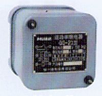
| Product nameŁş | GG-21 type reverse power relay | ||||||
| specificationŁş |  |
||||||
| CategoryŁş | low-voltage electrical apparatus -- power relay | ||||||
| PriceŁş | factory price | ||||||
| BrandŁş | |||||||
| Place of OriginŁş | China | ||||||
| Available QuantityŁş | batch | ||||||
| delivery cycleŁş | Spot goods (or inquire by telephone) | ||||||
|
|||||||
|
Generator power |
Rated current of engine (A) Ie=Pe/SQRT(3) Ve cos¦µ c(A) |
current transformer transformation ratio |
When the rated current of the generator is reached Current Transformer Current I2Ł¨AŁ© |
Percentage (%) of rated active power of relay at each setting position | ||
|
one |
two |
three | ||||
|
twenty-five forty fifty seventy-five one hundred one hundred and fifty two hundred two hundred and twenty-five two hundred and fifty three hundred four hundred five hundred six hundred six hundred and fifty seven hundred and fifty one thousand |
forty-five point two seventy-two point three ninety point four one hundred and thirty-five one hundred and eighty-one two hundred and seventy-one three hundred and sixty-two four hundred and seven four hundred and fifty-one five hundred and forty-two seven hundred and twenty-four nine hundred and three one thousand and eighty one thousand one hundred and seventy one thousand three hundred and fifty one thousand eight hundred and ten |
ten fifteen twenty thirty forty sixty eighty one hundred and twenty one hundred and twenty one hundred and twenty one hundred and fifty two hundred three hundred three hundred three hundred four hundred |
four point five two four point eight one four point five two four point five two four point five two four point five two four point five two three point three nine three point seven six four point five two four point eight one four point five two three point six two three point nine one four point five two four point five two |
seven point zero eight six point six six seven point zero eight seven point zero eight seven point zero eight seven point zero eight seven point zero eight nine point four three eight point five one seven point zero eight six point six six seven point zero eight eight point eight four eight point one eight seven point zero eight seven point zero eight |
ten point six two nine point nine eight ten point six two ten point six two ten point six two ten point six two ten point six two fourteen point one five twelve point seven seven ten point six two nine point nine eight ten point six two thirteen point two six twelve point two seven ten point six two ten point six two |
fourteen point one six thirteen point two one fourteen point one six fourteen point one six fourteen point one six fourteen point one six fourteen point one six eighteen point eight seven seventeen point zero two fourteen point one six thirteen point three one fourteen point one six seventeen point six eight sixteen point three six fourteen point one six fourteen point one six |
The GG-21 reverse power relay can be plugged into the corresponding socket for setting the power of a certain action.
In order to prevent the secondary winding of the current transformer from disconnecting and dangerous high voltage at the terminal, there is a spare plug in the fourth socket.
When converting loads, it is necessary to first insert the spare pin into the socket according to the required operating power. Only after doing so can the first pin be unscrewed and placed into the empty socket.
The relay has a delay that is inversely proportional to the operating power, which is obtained by rotating the aluminum disk of the relay rotation system between the permanent magnet poles of the relay.
By changing the stop block of the relay's moving contact, the set value of the action delay can be altered.
The stop lever is made in the shape of a pointer and can move along the dial. The dial is engraved with readings of 2s, 3s, 7s, 9s, and 12s. The time characteristic curves of 2s, 7s, and 12s are shown in Figure 2
When the contact is closed, the steel stop block located on the moving contact reaches the small magnet installed on the bottom plate of the contact system, thus
Attracted it, ensuring the reliability of circuit contact closure.
The relay magnet, rotating system, and contact system are installed on an aluminum silicon alloy frame, which in turn is mounted on an aluminum silicon alloy base. There are two terminal blocks on the base for connecting wires to relay coils and contacts, and the base is also used to secure relays to the distribution panel.
The relay has a steel casing to protect the mechanism from mechanical damage and prevent water droplets from entering.
The internal wiring of the relay is shown in Figure l Figure 1
Figure 2
3 Technical data
3.1 Rated voltage: 100V, 127V, 230V, 50HZ.
3.2 Rated current: 5A.
3.3 Maximum sensitivity angle: 30 ˇă -3 ˇă (i.e. current leads voltage by 30 ˇă).
3.4 The operating power is 6.4%, 9.6%, and 12.8% of the rated power at rated voltage and maximum sensitivity angle.
The action time at 3.5 1.2 times the action current and maximum sensitivity angle is 2s, 3s, 5s, 7s, 9s, and 12s.
3.6 Return coefficient, that is, the ratio of the return power of the rotating system returning to the initial position to the action power is not less than 0.6 (the action time is set between 2s and 5s).
When using a standard current transformer (COS ¦µ=0.8), the rated voltage of the generator is VH=400V. The actual operating power of the voltage transformer (400/127V) is shown in Table 1.
3.8 The external dimensions and opening dimensions of the relay are shown in Figure 3 and Figure 4.
Figure 3 Outline dimension diagram of GG-21 reverse power relay
Figure 4 Hole Size Diagram
4 Ordering Instructions
4.1 Product model and name.
4.2 Order quantity and specifications.
4.3 Wiring method. (Before or after the board).
HomeŁüQuality CommitmentŁüOrderingŁüPayment methodŁüproduct deliveryŁüsupportŁüDisclaimerŁüContact Us
Copyright®2011 www.91way.com Copyright.
PhoneŁş+86-21-66770508 +86-13916500500 FaxŁş+86-21-66108310
Email:91way@163.com Wechat:40606422
»¦ICP±¸2021005791şĹ ![]() »¦ą«Íř°˛±¸31010702003255şĹ
»¦ą«Íř°˛±¸31010702003255şĹ