1 Purpose
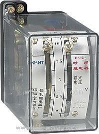
The DS-20 series time relay is used as an auxiliary component in various protection and automatic circuits, enabling adjustable delay in the operation of the controlled components.
Working principle and structure of DS-20 series time relay
2.1 The relay is a delayed suction electromagnetic relay. The relay has one instantaneous conversion contact, one sliding delay closing main contact, and one termination delay closing main contact.
When voltage is applied to both ends of the relay coil, the armature (iron core) is sucked in, the instantaneous dynamic contact is closed, the instantaneous dynamic contact is opened, and the delay mechanism starts to start at the same time. Under the action of the tension spring in the delay mechanism, after a set time, the sliding contact closes. After a certain amount of time, the endpoint contact will close. The period from the moment the voltage is applied to the coil to the time when the delayed closing contact is closed can be adjusted by moving the position of the static contact, and indicated directly on the scale of the relay by the pointer. When the coil is powered off, the chirp and delay mechanism instantly return to their original positions under the force of the tower shaped reaction spring.
2.3 Relays have two structures:
2.3.1 Protruding plug-in structure. The Aji JK-1 type housing is used, and its external drawing and opening diagram are shown in Appendix I. The internal wiring of the relay is shown in Figure 1.
2.3.2 Embedded plug-in structure (with/Q in the model). The Xuji A11K shell is used, and its external drawing and opening diagram are shown in Appendix II. The internal wiring of the relay is shown in Figure 2.
If the wiring method behind the board needs to be changed to the wiring method in front of the board, a wiring socket and a middle frame in front of the board should be added, as shown in Appendix II.

Figure 1 Protruding internal wiring diagram * R is the external resistor (attachment), and accordingly: DS-21-24 DS-21/C-24/C DS-25-28
Figure 2 Embedded internal wiring diagram * R is the external resistor (attachment), and accordingly DS-21/Q~DS-24/Q DS-21C/Q~DS-24C/Q DS-20/Q~DS-28/Q
Click on the above image to view a larger picture
3 model specifications (see Table 1)
|
model |
Time setting range (S) |
Rated DC voltage (V) |
Rated AC voltage (V) |
|
DS-21Ł¬DS-21/C |
0.2-1.5 |
24Ł¬48Ł¬110Ł¬220 |
|
|
DS-22Ł¬DS-22/C |
1.2-5 |
|
DS-23Ł¬DS-23/C |
2.5-10 |
|
DS-24Ł¬DS-24/C |
5-20 |
|
DS-25 |
0.2-1.5 |
|
110Ł¬127Ł¬220Ł¬380 |
|
DS-26 |
1.2-5 |
|
DS-27 |
2.5-10 |
|
DS-28 |
5-20 |
Note: C is a long-term charged type
4 DS-20 series time relay technical data
4.1 Action value of relay: not exceeding 70% of the rated voltage for DC relays; For long-term charged DC relays, the rated voltage shall not exceed 75%; For AC relays, the rated voltage should not exceed 85%.
4.2 Return value of relay: not greater than 5% of rated voltage.
The delay consistency of the main contact of the relay shall not exceed the provisions in Table 2.
|
Delay setting range (s) |
Delay consistency (s) |
|
0.2-1.5 |
zero point zero seven |
|
1.2-5 |
zero point one six |
|
2.5-10 |
zero point two six |
|
5-20 |
zero point five |
Note: 1) Delay consistency refers to the difference between the maximum and minimum action times measured 10 times at the same time set point.
2) The parameters specified in Articles 1, 2, and 3 are tested under the condition of an ambient temperature of+20oCK2oC.
The average error of the delay setting value of the main contact of the 4.4 relay shall comply with the following regulations: the average error of the maximum delay setting value less than 5s shall not exceed K10%, and the rest shall be K5%.
4.5 Thermal stability: When the surrounding medium temperature is+40oC, the coil of a DC relay can withstand 110% of the rated voltage for 1 minute, and the coil temperature rise does not exceed 65K; for an AC relay, the coil can withstand 110% of the rated voltage for 1 minute, and the coil temperature rise does not exceed 65K; for a long-term charged DC relay, the coil can withstand 110% of the rated voltage for a long time, and the coil temperature rise does not exceed 65K.
4.6 Power consumption at rated voltage: not more than 10W for DC relays, not more than 35VA for AC relays, and not more than 7.5W for long-term charged DC relays.
4.7 Contact breaking capacity: In DC inductive load circuits with voltage not exceeding 250V, current not exceeding 1A, and time constant not exceeding 0.005s, the breaking capacity of the main contact and instantaneous contact is 50W.
4.8 The delayed main contact allows a long-term current of 5A to pass through.
4.9 Dielectric Strength: The conductive and non-conductive parts of the relay, as well as the coil circuit and contact circuit, can withstand an AC of 50Hz and a voltage of 2kV for 1 minute without breakdown or flashover.
4.10 Electrical lifespan: 5000 cycles.
4.11 The relay operates reliably within the ambient temperature range of -20oC to+40oC.
4.12 Relay weight: not exceeding 0.7Kg.
5 Ordering Instructions
Please specify when placing an order
5.1 Name and model of relay;
5.2 Rated parameter values;
5.3 Order quantity.
5.4 Delivery method.