1 Purpose
1.1 DD-1 type grounding relay (hereinafter referred to as relay) is an instantaneous overcurrent relay used for zero sequence overcurrent protection of high-voltage three-phase AC generators and motors in small grounding current power systems.
1.2 Relay coil connected to zero sequence current transformer (cable type, busbar type) or zero sequence current protection composed of three phase current transformers.
When the zero point of the protected motor is grounded through impedance, the relay is connected to the differential circuit of the inverter.
When the relay is connected to a zero sequence current filter composed of three phase current transformers, a blocking relay should also be connected to prevent misoperation caused by unstable currents due to external transient short circuits.
2 Structure and principle
2.1 Relays are instantaneous actions constructed according to electromagnetic principles. The electromagnetic system has two coils, and when the coils pass through current, they form a magnetic flux of electromagnetic torque in the magnetic conductor.
2.2 As relays are used for grounding protection in small grounding current systems, high sensitivity is required. Therefore, in addition to using a spring with a small reaction torque, compensation windings are added to both coils. After they are connected in series, they form a closed loop through a capacitor (C=0.47 ¦Ě f) to compensate for the reactance of the magnetizing coil, reducing the power required to generate the same magnetic flux in the magnetic conductor, improving the sensitivity of the relay, and reducing losses.
2.3 The outgoing line of the relay coil is connected to the terminal of the relay base, and a connecting piece is installed to change the coil from series to parallel, thus doubling the setting value of the relay.
The adjustment of the setting current of the 2.4 relay can be achieved by rotating the pointer on the dial to change the reaction torque of the balance spring. The relay has a dynamic contact.
The internal wiring of the 2.5 relay is shown in Figure 1.
2.6 Relays must be installed vertically on the screen board and can be wired in front or behind the board.
2.7 Relays have three structures: A11K, A11H, and A1lQ,
Appendix II.
Figure 1 Internal wiring diagram of DD-1 grounding relay (back view)
Technical data of DD-1 grounding relay
The setting range of relay operating current and coil impedance value are shown in Table 1.
|
model |
Setting range
Ł¨mAŁ© |
Coil series connection |
Parallel connection of coils |
|
Action current (mA) |
Impedance (¦¸) |
Action current (mA) |
Impedance (¦¸) |
|
DD-1ŁŻ40 |
10~40 |
10~20 |
one hundred |
20~40 |
twenty-five |
|
DDˇŞ1ŁŻ50 |
12.5ˇ«50 |
12.5ˇ«25 |
eighty |
25~50 |
twenty |
|
DDˇŞ1ŁŻ60 |
15~60 |
15~30 |
sixty |
30~60 |
fifteen |
3.2 When relays of various specifications are connected in series or parallel with the coil, their impedance angle is+35 ˇă.
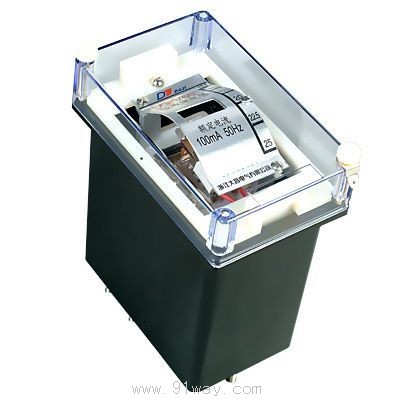
3.3 Rated current 100mA, frequency 50Hz.
The accuracy of the scale on any set point shall not exceed ˇŔ 6%.
3.5 The variation in motion during five measurements at the same set point shall not exceed 6%
3.6 The return coefficient shall not be less than 0.5.
At the minimum setting current, the power consumption of the relay shall not exceed 0.015VA.
3.8 When the setting current is 1.2 times, the action time shall not exceed 0.3 seconds, and when the setting current is 3 times, the action time shall not exceed 0.1 seconds.
When the voltage does not exceed 250V and the current does not exceed 0.5A, the breaking capacity of the relay contacts is 20W in a DC inductive load circuit (time constant of 5 ˇÁ 10-3s) and 100VA in an AC circuit.
The dielectric strength between each circuit of the 3.10 relay and the metal shell can withstand AC 50Hz, voltage 2kV, and no breakdown or flashover phenomenon after a 1-minute test.
3.11 The weight of the relay shall not exceed 1kg.
4 Ordering Instructions
4.1 Relay name and model.
4.2 Maximum setting current of relay (mA).
4.3 Number of relays.