Purpose:
The ZFT9 synchronous pulse transmission device is used in the three-phase system of ships. Based on the voltage difference, phase difference, frequency, and closing time of the circuit breaker between the generator and the power system, it sends closing pulses to the generator to ensure that it avoids the impact during parallel operation. The device can be used not only for three-phase generators, but also for single-phase systems.
Relay model name:

Working Principle:
The device compared the frequency and phase relationship between the power supply system and the generator to be put into operation, and issued a closing pulse to close the contacts of the generator circuit breaker approximately at zero crossing of the slip voltage. The lead time (i.e. circuit breaker closing delay) is adjustable from 30ms to 450ms. If the frequency difference is greater than ± 0.5Hz, the closing pulse is locked internally by the device.
When the external button S is pressed to allow the device to start working, a closing pulse can be issued. This button will remain in place until the generator circuit breaker is closed.
Main technical parameters of ZFT9 (PIG) synchronous pulse transmission device:
5.1 Rated voltage and frequency
a) AC 50Hz 380V or 100V;
b) AC 60Hz 440V or 110V.
5.2 The frequency difference during device control synchronization shall not exceed ± 0.5Hz.
The lead time of the device is adjustable from 30 ± 5 to 450 ± 50ms.
5.4 The device closing pulse time is greater than or equal to 700ms.
5.5 Power consumption
The power consumption of the generator voltage circuit under rated voltage of the device shall not exceed 3VA (not exceeding 6VA during operation), and the system voltage circuit shall not exceed 2VA.
5.6 Contact Performance
The maximum disconnection of the relay contact at the outlet of the device is AC 380V, 3A or 220V, 7.5A (coso=1).
5.7 Dielectric Strength
The electrically unrelated conductive circuit parts in the device, as well as the conductive parts connected together, should be able to withstand an AC test voltage of 2.5kV (effective value) and 50Hz for 1 minute without insulation breakdown or flashover phenomenon for non-conductive metal parts (to ground).
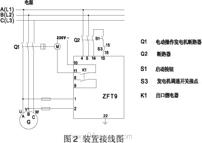
Wiring diagram behind the relay:
The wiring diagram is shown in Figure 2.
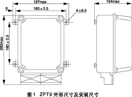
Relay external dimensions and opening dimensions:
The device is of static type, with a protruding installation structure and front board wiring method. Its appearance and installation dimensions are shown in Figure 1,
Ordering instructions:
6.1 Product model, name, and rated frequency.
6.2 Order code.
7VE8033 (voltage 400V/450V)
7VE8043 (voltage 100V/110V) (8033-Z)

 Your location:Home → Special electrical appliances → Marine power supply → ZFT9(PIG) Synchronous pulse transmission device

 No image available
 Related Products:
 explosion-proof component
  Ex-proof electrical equipment
 沪公网安备31010702003255号

