
| Product name: | JKW type reactive power automatic compensation controller | ||||||
| specification: |  |
||||||
| Category: | low-voltage electrical apparatus -- Compensation equipment | ||||||
| Price: | factory price | ||||||
| Brand: | Shanghai | ||||||
| Place of Origin: | China | ||||||
| Available Quantity: | batch | ||||||
| delivery cycle: | Spot goods (or inquire by telephone) | ||||||
|
|||||||
Features and functions
1. The physical quantity sampled by this controller is reactive power. It adjusts the switching of compensation capacitors based on the reactive power of the power grid, making it suitable for power grids of various capacities, without being limited by the switching of capacitors and changes in sampling current. In use, it generally does not require adjustment and can work stably.
2. The main feature of this machine is the adjustable threshold for undercurrent. When the grid load is low (sampling current<0.5A), users can make appropriate adjustments according to the situation to meet the compensation needs of specific small load conditions
3. The number of output channels can be set to 2-10 as needed.
4. The output circuit adopts a cyclic working mode of "connect first, disconnect first" to ensure that each contactor and capacitor operates the same number of times, extending the fault free working time.
5. It has overvoltage protection function to prevent capacitors from being damaged during operation under overvoltage conditions.
6. "Auto/Manual" is operated by the "Function Selection Key" for easy debugging.
7. Automatically distinguish the positive and negative directions of the incoming phase, making installation and debugging very convenient.
Terms of Use
1. The ambient air temperature ranges from -20 ℃ to+40 ℃.
2. The relative temperature should not exceed 50% at 40 ℃; At 20 ℃, it does not exceed 90% and does not condense.
3. The surrounding environment is free of corrosive gases, conductive dust, and explosive and flammable media.
4. The altitude fluctuation range shall not exceed 2000-2500m.
5. 2
The voltage fluctuation range shall not exceed+-10%.
6. The vibration frequency range of the installation site is 10-150Hz, and the maximum vibration acceleration is not greater than 5m/s.
Technical parameters:
1. Execution standard: JB/T9663-1999
2. Planting and adjustable range.
a、 Investment threshold: 0.93 (0.9~1.0).
b、 Cut off threshold: -1.0 (adjustable from -1.0 to -0.98).
c、 Undercurrent: When displayed as<0.5A, appropriate adjustments can be made to achieve compensating reactive power.
d、 Delay time: 20S (adjustable from 5S to 100S).
e、 Overvoltage protection:
When the rated voltage is 380V, it is 440V (adjustable from 400V to 460V).
When the rated voltage is 220V, it is 254V (adjustable from 230V to 265V).
3. Basic parameters
a、 Rated working voltage: AC 50HZ 380V, (220V optional).
b、 Current sampling input: ≤ 5A (AC).
c、 Overvoltage interruption time: not more than 1 minute.
d、 Output relay electric shock capacity: 1.5A (250V).
e、 Sensitivity: 0.1A.
f、 Dielectric strength: 2500V (AC).
g、 Protection level: not less than IP40.
h、 Work status: Continuous work system.
Size and installation
1. The external dimensions and installation dimensions are shown in the diagram.
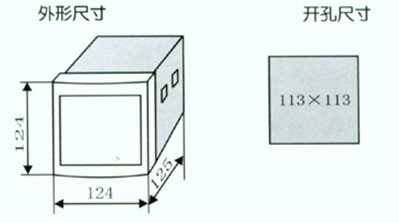
1. When installing, insert the hook of the installation accessory into the hole on the side of the controller, and turn the screw on the accessory to fix the machine on the screen.
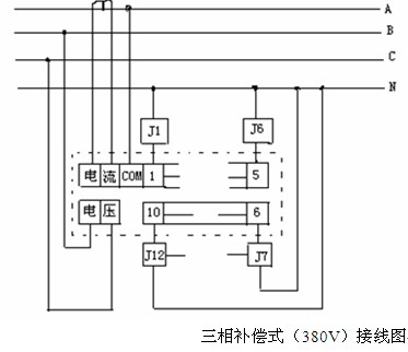
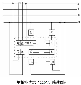
wiring
1. The rated voltage of the AC contactors (J1, J2...) in the following figure is 220V, and their common line is connected to N (neutral line). If a 380V contactor is used, its common line should be connected to phase B or C.
2. When wiring, please pay attention to not connecting the current input line and the voltage input line incorrectly! Otherwise, it will burn down the machine.
3. The sampling current Is must be taken from the total load power line and not from the capacitive screen.
4. Three phase compensation type (380V), the sampling voltage Us and sampling current Is must be taken from different phase power sources.
Single phase compensation type (220V), the sampling voltage Us and sampling current Is must be taken from the same phase power supply.
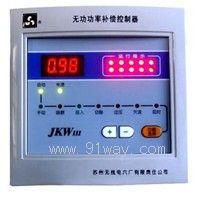
Panel functions, debugging, and operation
1. Route adjustment: After power on, press the "Function Selection" button to turn on the "Route" indicator light. Press the "+" or "-" adjustment button to display the required route on the digital display. This function is only effective for 25 seconds of power on and automatically locks the route when it expires.
2. Cut off threshold adjustment: Press the "Function Selection" button to turn on the "Upper Limit" indicator light, and press the "+" or "-" adjustment button to display the desired value on the digital display.
3. Input threshold adjustment: Press the "Function Selection" button to turn on the "Lower Limit" indicator light, and press the "+" or "-" adjustment button to display the desired value on the digital display.
4. Overvoltage protection adjustment: Press the "Function Selection" button to turn on the "Overvoltage" indicator light, and press the "+" or "-" adjustment button to display the desired value on the digital display.
5. Delay time adjustment: Press the "Function Selection" button to turn on the "Delay" indicator light, and press the "+" or "-" adjustment button to display the desired value on the digital monitor.
6. Automatic operation, shift the gear switch to the "automatic" position, run the indicator light, and the controller automatically switches capacitors.
7. Manual operation, shift the gear switch to the "manual" position. When the "running" indicator light is on in the "running" position, press the "+" or "-" adjustment button to turn on or off the capacitor.
8. If there is no button operation within 20 seconds when the shift switch is turned to the "automatic" position, it will automatically return to the running state, and the "running" indicator light will be on.
9. Memory parameters: The parameters set by the user are saved in memory and will not be lost in case of power failure. To restore the factory settings, press and hold the "Function Selection" button when powering on again.
Usage and Instructions
1. Before powering on, check whether the wiring terminals are connected accurately.
2. The shift switch must be set to "automatic" during operation.
3. The controller is factory preset with control parameters that can be adjusted according to general user requirements, without the need for further adjustments, and can work stably; If users need to make actual adjustments on site, they should refer to the instructions or be guided by technical personnel. Note that the "delay" time should not be less than 15 seconds to protect the capacitor.
Common Fault Analysis
1. The following controllers should be considered as normal phenomena:
a、 The power factor of the power grid is very low, the controller does not operate, and the undercurrent light is on (<0.1). When the load current is sufficient, it will naturally activate.
b、 The power factor of the power grid is very low, the controller does not operate, and the overvoltage light is on. After the voltage returns to normal, it will take action.
c、 The power factor of the power grid is very low, and all lines have been put into operation. It is normal for the input lights to still be on (requiring an increase in capacitance).
d、 The power factor of the power grid is ahead, the reactive power meter reverses slowly, the controller does not cut off, and if the lead value exceeds the set threshold, it will be cut off.
2. The following phenomena are generally wiring errors:
a、 The power factor of the power grid is low, and the controller's input light does not light up and is not activated.
b、 The power factor of the power grid is not low, and the controller's input light is on while all channels are turned on, resulting in the power factor of the power grid leading but not cutting off.
3. The following phenomena can be determined as controller faults:
a、 Put the light on but not put it in.
b、 The overvoltage light is on but not turned off.
c、 The cutting sequence is disorderly and disorganized.
d、 The wiring is correct, the fuse is intact, but the controller is unresponsive and does not operate.
4. If any abnormal phenomenon occurs, please contact the after-sales service department immediately, and we will do our best to serve you.
Precautions
1. A controller with a compensation method of "three-phase" should be used on three-phase symmetrical loads, otherwise it will cause uneven compensation among the phases. For three-phase asymmetric loads, a "single-phase" controller should be selected with phase compensation.
2. The controller with a compensation method of "single-phase" can be used for three-phase loads and can also be used for phase separation compensation of asymmetric loads.
3. If an additional capacitor is added, it will be overcompensated, and if an additional capacitor is added, it will be undercompensated. The reactive power meter rotates quickly, and at this time, the capacity of each capacitor added should be reduced, regardless of the compensation controller.
4. Overvoltage protection adjustment: Press the "Function Selection" button to turn on the "Overvoltage" indicator light, and press the "+" or "-" adjustment button to display the desired value on the digital display.
5. Delay time adjustment: Press the "Function Selection" button to turn on the "Delay" indicator light, and press the "+" or "-" adjustment button to display the desired value on the digital monitor.
6. Automatic operation, shift the gear switch to the "automatic" position, run the indicator light, and the controller automatically switches capacitors.
7. Manual operation, shift the gear switch to the "manual" position. When the "running" indicator light is on in the "running" position, press the "+" or "-" adjustment button to turn on or off the capacitor.
8. If there is no button operation within 20 seconds when the shift switch is turned to the "automatic" position, it will automatically return to the running state, and the "running" indicator light will be on.
9. Memory parameters: The parameters set by the user are saved in memory and will not be lost in case of power failure. To restore the factory settings, press and hold the "Function Selection" button when powering on again.
Usage and Instructions
1. Before powering on, check whether the wiring terminals are connected accurately.
2. The shift switch must be set to "automatic" during operation.
3. The controller is factory preset with control parameters that can be adjusted according to general user requirements, without the need for further adjustments, and can work stably; If users need to make actual adjustments on site, they should refer to the instructions or be guided by technical personnel. Note that the "delay" time should not be less than 15 seconds to protect the capacitor.
Home|Quality Commitment|Ordering|Payment method|product delivery|support|Disclaimer|Contact Us
Copyright®2011 www.91way.com Copyright.
Phone:+86-21-66770508 +86-13916500500 Fax:+86-21-66108310
Email:91way@163.com Wechat:40606422
沪ICP备2021005791号 ![]() 沪公网安备31010702003255号
沪公网安备31010702003255号