
| Product name�� | PDK Type II Reactive Power Compensation Comprehensive Measurement and Control Instrument | ||||||
| specification�� |  |
||||||
| Category�� | low-voltage electrical apparatus -- Compensation equipment | ||||||
| Price�� | factory price | ||||||
| Brand�� | Shanghai | ||||||
| Place of Origin�� | China | ||||||
| Available Quantity�� | batch | ||||||
| delivery cycle�� | Spot goods (or inquire by telephone) | ||||||
|
|||||||
The PDK-II reactive power compensation monitor integrates phase separation compensation and centralized compensation, cyclic switching and coding switching, static compensation and dynamic compensation, and can meet the setting requirements of almost all users.
Usage:
1. Environmental temperature: not exceeding -20 ��~+55 ��
2. Environmental humidity: not exceeding 90% at 20 ��
3. Surrounding environment: No corrosive gases. No conductive dust, no presence of explosive or flammable media
4. Altitude: not exceeding 2000 meters
Technical parameters of PDK II reactive power compensation comprehensive measurement and control instrument:
1. Rated working voltage: 3 �� 220V/AC 50HZ
2. Current sampling input: 3 �� 0-5A/�� 0.1 ��
3. Input threshold: continuously adjustable from 0.85 to 1.0, factory setting value is 0.95
4. Cut off threshold: -1.0 to -0.85 continuously adjustable, factory set value is -1.0
5. Action error: �� 2.5
6. Overvoltage action value: adjustable from 240V to 280V, factory set value is 254V
7. Overvoltage interruption time: �� 1 minute
8. The on/off delay time of the output circuit is adjustable from 5 seconds to 100 seconds statically, with a factory set value of 20 seconds
Dynamic 20 milliseconds to 5 seconds, factory set value is 100 milliseconds
9. Output capacity: Static relay 2A/250VAC
Dynamic level output 60mA, 12VDC
10. Dielectric strength: �� 2500V
11. Protection level: not less than IP40
12. Whole machine power consumption: �� 10W
Installation and wiring:
1. The appearance of this machine is embedded, with a hole size of 138 �� 138mm. The equipment can be fixed on the compensation screen using the fastening accessories attached to this machine.
2. Attention should be paid to the connection of voltage and current sampling signals: the three phases are allowed to be exchanged, and the two wires of the current transformer are allowed to be exchanged, but the connection phases of voltage and current must correspond one-to-one.
3. The connection method of the controller output line: The number on the controller panel should correspond one-to-one with the number of the output terminal and AC contactor.
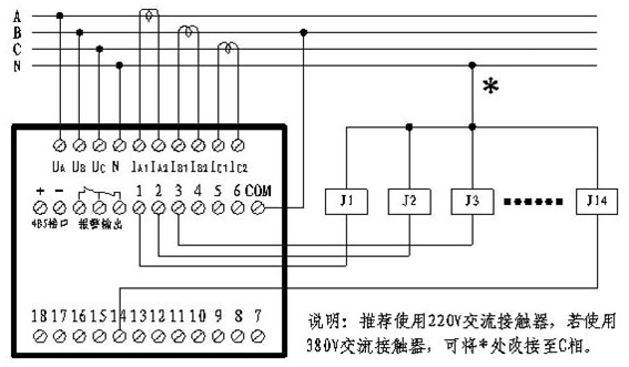
a�� Compensation capacitor connection: 1111 code is used for cyclic switching
b�� Code switching: If 1222... code is used, it corresponds to the bit weight of the output terminal. For example, the first output is connected to a 15kV capacitor, the second output is connected to a 2x15 capacitor equal to 30kV capacitor, and the third output is also connected to a 2x15 capacitor equal to 30kV capacitor, and so on. If using code 1244..., if the first circuit is connected to a 15kV capacitor, the second circuit should be connected to a 2x15 capacitor equal to 30kV capacitor, the third circuit should be connected to a 4x15 capacitor equal to 60kV capacitor, and the fourth circuit should still be connected to a 4x15 capacitor equal to 60kV capacitor, and so on.
c�� Special attention should be paid that if 1111... code is selected in the encoding switching, a special "first switching, then power" function can be achieved. For example, if the switching order is 1, 2, 3... 16, then the switching order is 16, 15, 14... 1.
d�� The shared output can control capacitors with a rated voltage of 380 volts, connected in a "��" configuration;
The shunt output can control capacitors with a rated voltage of 220 volts, connected in a "Y" configuration.
Power on operation:
The device is powered on for the first time. To ensure correct wiring and capacitor configuration, it is recommended to enter the "self check" working state (see next section for details).
After the controller is powered on, it automatically enters the "running" state (default working state), and users can enter different working states according to their needs. Please refer to the operation diagram for the operation steps.
Self inspection work:
When in operation, press the "ESC" key to enter the "main menu", then press the "��" and "��" keys to move the cursor up and down, select "self-test", and then press�� �L�� The key can enter the self-test working state. The self checking method of the measuring and control instrument is to test switching one by one, and its functions include:
1. Check the input of the measuring and controlling instrument. If the current sampling is found to be reversed, the monitoring instrument will automatically adjust it. If a user wiring error is found, the monitoring instrument will display "input abnormal". In self checking, there are two situations where "input abnormality" occurs: A. The phase line is connected incorrectly, and the voltage and current lines do not correspond one-to-one. B�� Large inductive or capacitive loads.
2. Detect the output of the monitoring instrument, check the C/K value of the compensation capacitor, and use it as the basis for controlling switching at low currents. At the end of the self-test, the measuring and control instrument will present a detection report, showing the output terminal number of the capacitor with reduced capacity and open circuit. After the self check is completed, the monitoring device will automatically enter the running state.
Common problems and solutions:
1. The monitor displays "low current": indicating that the total current is small, and the monitor compensates according to the reactive current method. Therefore, there may be a situation where the power factor is small but the reactive current is not large, and the capacitor is not connected. Due to the low reactive power at this time, users do not need to worry about the power factor value being too small.
2. The monitor displays "input abnormality": it should be checked whether the input voltage line corresponds one-to-one with the input current line; There are significant inductive and capacitive loads.
3. The monitor displays "oscillation": indicating that the controller has invested too many capacitors and removed too few capacitors, so it is necessary to reduce the capacity of the capacitors invested in each step.
4. The monitor displays "too inductive": indicating that all capacitors have been put into operation, but the power grid is still inductive, due to a decrease in capacitor capacity or a design capacity of the compensation cabinet that is too small. The capacitor should be replaced or the capacity of the capacitor should be increased for each step.
5. The monitor displays "voltage distortion": indicating severe harmonic distortion on the power grid, and efforts should be made to eliminate it, otherwise it will damage the compensation capacitor.
If the monitoring device is not working properly, you can first follow the operation in Section 12 to restore the factory settings. Generally, it can work normally. If the monitoring device is still not functioning properly, please contact our after-sales service department, and we will do our best to serve you.
Features:
1. The application of new AC radio wave analysis technology can ensure the correctness of power grid parameter settings and the stability of operation in harsh environments such as strong interference and strong harmonics.
2. The three-phase power grid has successfully solved the problem of three-phase imbalance compensation through independent detection of phase separation and the combination of "co compensation" and "sub compensation" for switching.
3. The reasonable application of two compensation methods: high current controls the input or removal of compensation capacitors based on the power factor, while low current controls the input or removal of capacitors based on the reactive power.
4. Complete capacitor capacity, C/K value detection, and capacitor protection functions. Provide two working modes, automatic and manual, and offer various capacitor protection functions such as "overvoltage" and "harmonic".
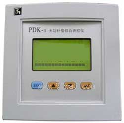
5. Large screen LCD display, fully Chinese menu operation interface, real-time display of power factor, current, and voltage for three phases, as well as preset parameter display.
6. Power grid abnormal alarm: provides text display and alarm relay output for overvoltage, overcurrent, undercurrent, input abnormality, switching oscillation, and excessive inductance, and provides voltage distortion (harmonic) alarm output function.
7. Manual compensation control mode, for application during debugging.
8. The settings for loop switching, coding switching, and code system selection can be easily achieved through the internal control menu. 16 output channels can be combined arbitrarily, which can meet the setting requirements of almost all users.
9. Capacitor harmonic value over limit protection.
10. Reactive power sampling and compensation control method within the full current range.
11. Output form: Static: Relay output Dynamic: Level output.
Home��Quality Commitment��Ordering��Payment method��product delivery��support��Disclaimer��Contact Us
Copyright®2011 www.91way.com Copyright.
Phone��+86-21-66770508 +86-13916500500 Fax��+86-21-66108310
Email:91way@163.com Wechat:40606422
��ICP��2021005791�� ![]() ����������31010702003255��
����������31010702003255��