|
Product name: |
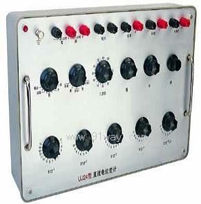
UJ24 Type DC Potentiometer
|
|
specification: |
|

 Zoom in on the image Zoom in on the image |
|
Category: |
instrumentation and meters
-- voltmeter |
|
Price: |
factory price |
|
Brand: |
|
|
Place of Origin: |
China |
|
Available Quantity: |
batch |
|
delivery cycle: |
Spot goods (or inquire by telephone) |
|
| |
Shanghai Beiyuan Industry and Trade Co.,Ltd
+86-21-66770508
+86-13901609058 |
 91way@163.com 91way@163.com
 13901609058(Wechat) 13901609058(Wechat)
|
|
|
|
UJ24 Type DC PotentiometerDetailed product description:

1、 Purpose:
The UJ24 type DC potentiometer is a precision high potential DC potentiometer that can directly measure DC potential. Equipped with standard resistors, it can measure DC current, resistance, and power.
2、 Principle
This potentiometer adopts the principle of compensation method to compare the measured electromotive force with a constant standard electromotive force, which is a high-precision method for measuring electromotive force.
(1) There is no need to measure the current in the circuit, just measure the ratio of RK=to RNR.
(2) When fully compensated, no current flows between the measuring circuit and the measured circuit, and the measuring circuit does not consume the energy of the measured circuit.
(3) The accuracy of the measurement depends on the accuracy of the ratio of the standard battery electromotive force EN and the compensation resistor RK of the measured electromotive force to the standard battery electromotive force compensation resistor RN, as well as the stability of the operating current. Due to the high manufacturing accuracy and stability of the standard battery RK and RN resistors, the accuracy and stability of the measurement are also determined. Under the conditions of using high-sensitivity galvanometers and high stable current operation, the measurement results can be extremely accurate.
3、 Line and structure
The working current of UJ24 type DC potentiometer is 0.1 milliampere, with 10000 ohms per volt.
The potentiometer has six measuring plates, and its range of measuring electromotive force is as follows:
The first measurement of the ten pin disk is 0.1 volts x 20, consisting of 15 pieces of 1000 ohms
The second measurement of the ten pin disk is 0.01 volts x 10, consisting of 10 pieces of 100 ohms
The third measurement consists of 20 10 ohm panels measuring 0.001 volts x 10 on a ten pin disk
The fourth measurement of the ten pin disk is 0.0001 volts x 10, consisting of 20 pieces of 1 ohm
The fifth measurement of the ten pin disk is 0.00001 volts x 10, consisting of 20 pieces of 0.1 ohms
The working current consists of three disks, with adjustable ranges as follows:
17×240+17×14.5+(0~20)Ω
The "Unknown 1", "Unknown 2", and "Electrometer" each consist of two terminal knobs for connecting the measured potential and external zero point indicator. Except for the "Electrometer" terminal knob, all others are marked with a "+-" polarity symbol to avoid polarity errors during wiring.
The "standard", "unknown", and "disconnect" switches can be used to connect standard batteries, measure electromotive force, and disconnect measurement lines; The "coarse", "medium", "fine", "short circuit", and "output" switches can be used to select whether the "zero pointer" protection is turned on, through, or short circuited, or to select whether the "unknown" terminal outputs a potential equal to the reading on the measuring dial.
The structure of the potentiometer: All ten input disks are made of high insulation materials, and the electric brushes and contacts are made of silver materials.
4、 Technical features and kits
(1) Main characteristics of UJ24 high resistance potentiometer:
(1) The upper limit of this instrument is 1.61110 volts, and the minimum division value is 10 microvolts. If equipped with a 0.01 level voltage divider to expand the measurement range, the measurement limit of the potentiometer can be increased to 600 volts.
(2) When measuring under normal conditions at a temperature of+17 ℃~23 ℃ and a relative humidity below 80%, the maximum absolute error within the entire measurement range of the potentiometer should not exceed the calculated value using the following formula:
δ=± (UX × 10-4 ± 5 × 10⁻⁶) (volts)
In the formula, UX represents the reading value of UJ24 on the reading dial (in volts)
(3) The insulation strength between the potential difference meter circuit and the casing can withstand an actual sinusoidal AC voltage of 2000 volts at a power frequency of 50 Hz for 1 minute without breaking through.
(4) Dimensions of potential difference meter: 450 × 300 × 145 millimeters
(5) Potentiometer weight: 4.5 kilograms
(2) Equipment used in conjunction with a potential difference meter:
(1) 0.01 or 0.02 level voltage divider box.
(2) 0.01 or 0.02 level standard resistance.
5、 Usage Regulations
(1) Measurement of electromotive force:
Before using the potential difference meter, first place the "standard", "unknown", and "off" conversion switches in the "off" position, set the "coarse", "medium", "fine", "short circuit", and "output" conversion switches in the "coarse" position, and then connect the measured electromotive force to the corresponding terminal knobs in positive and negative polarity.
Turn the state switch of the whole machine to the "standard" position, and turn the "coarse", "medium", and "fine" adjustment knobs (resistors) of the working current to make the ammeter point to zero. Set the status switch of the ammeter to the "fine" position, and further adjust the "coarse", "medium", and "fine" knobs to make the ammeter point to zero. Turn the whole machine state conversion switch to the "unknown" position, place the ammeter state conversion switch in the "coarse" and "fine" positions, adjust the five ten inch measuring dial knobs to make the ammeter point to zero. The reading indicated by this row of knobs is the measured electromotive force value.
(2) Measurement of high voltage:
(1) When the measured voltage is above 1.61110 volts, a rated resistance input voltage divider box should be used.
(2) The negative terminal of the voltage divider box is connected to the "unknown" negative terminal of the potentiometer, while the other end of the "unknown" potentiometer is selected to be connected to an appropriate terminal of the voltage divider box multiplier (× 500, × 200, × 100, × 20, × 10) based on the measured voltage value and the reading of the upper limit of the potentiometer measurement.
(3) Adjust the working current.
(4) Measure the corresponding voltage drop determined on the voltage divider box.
(5) The reading on the potentiometer multiplied by the multiplier determined on the voltage divider box is equal to the measured voltage value.
6、 Precautions
(1) When measuring high voltage, special attention should be paid to the circuit structure and positive and negative polarity markings of the voltage divider box. The terminals of the measured high voltage and the potential difference meter must not be connected incorrectly.
(2) When measuring voltage, current, and power with a potentiometer, the rotation of each knob in the measuring section should start from the first position and rotate sequentially.
(3) When using a potentiometer with a kit, it is necessary to pay attention to the insulation resistance between the connecting wires, potentiometer, and various parts of the kit, which should not be less than 500 megaohms.
(4) When adjusting the working current of a potentiometer during calibration, it should be done in the order of coarse, medium, and fine.
7、 Maintenance and upkeep
1. If the potentiometer is left unused for a long time, oxidation may occur between the brush and the contact surface, causing poor contact. When using, all rotary switches should be rotated several times to ensure good contact. If the contact between the electric brush and the contact surface is not good, it must be cleaned with gasoline to restore the contact, and then coated with a thin layer of acid free pure Vaseline for protection.
2. Potentiometers should not be subjected to strong vibrations and impacts. It should be stored indoors at a temperature of+15 ℃~+30 ℃, with a relative humidity below 80% and no corrosive gases.
3. The potentiometer should be regularly calibrated at least once a year.
 Related Products:
- Related articles:
