
| Product name: | CJ11A-G series maintenance free electric motor operating mechanism | ||||||
| specification: |  |
||||||
| Category: | spare parts and accessories -- Electric operating mechanism | ||||||
| Price: | factory price | ||||||
| Brand: | |||||||
| Place of Origin: | China | ||||||
| Available Quantity: | batch | ||||||
| delivery cycle: | Spot goods (or inquire by telephone) | ||||||
|
|||||||
Overview of CJ11A-G series maintenance free electric motor operating mechanism
At present, there are inevitable defects in the mechanisms used for high-voltage isolating switches in China, such as an open transmission structure that requires regular lubrication or maintenance, poor environmental adaptability, low protection level, loud noise during operation, and short service life. To solve these problems, our factory organized scientific research efforts to develop the CJ11A-G series maintenance free electric motor operating mechanism. The mechanical deceleration part of this mechanism adopts a fully enclosed structure for maintenance free operation to replace the traditional open structure. Its maintenance free, high reliability, and strong interchangeability make it the preferred product to replace traditional mechanisms.
2. Environmental conditions for use
2.1 Same as the high-voltage isolation switch and grounding switch provided.
The voltage variation range of the power supply is 85% to 110% of the rated voltage.
3. Structure and Performance Characteristics
3.1 CJ11A-G series maintenance free electric motor operating mechanism (hereinafter referred to as CJ11A-G mechanism), driven by an AC motor, is used to operate high-voltage isolation switches and grounding switches through a fully enclosed gear and worm gear reduction part. It can be remotely controlled, electrically controlled locally, or manually operated using a handle. Manual and electric interlocking devices are installed inside the box to achieve electrical interlocking between manual and electric operations.
The core components of the CJ11A-G mechanism (gears and worm gear reduction parts) are sealed in a high-quality aluminum alloy box as a whole, which is not affected by the external environment. The transmission of the mechanism is smooth, noiseless, does not require any lubricating grease, and completely achieves maintenance free operation. Due to the use of high-quality aluminum alloy materials for both the casing and motor housing, the mechanism is lightweight, has good heat dissipation performance, and excellent corrosion resistance.
3.3 In order to meet the requirements of various installation scenarios and installation methods, as well as the need for users to replace old mechanisms, the CJ11A-G mechanism considers different installation methods, rotation angles, and center height requirements, and can almost be matched with various series of high-voltage isolation switches. After attaching various mounting plate accessories to the operating mechanism, the installation size is exactly the same as that of the old model mechanism (such as CJ2, CJ5, CJ6, etc.), and no adjustment is required when replacing the old mechanism.
4. Technical parameters
4.1 Output torque: 200N. m~1000N. m
4.2 Output angle: 180 ° or 90 °
4.3 Opening time: 6 ± 1.5 seconds or 9 ± 2 seconds
4.4 Closing time: 6 ± 1.5 seconds or 9 ± 2 seconds
4.5 Motor power: 200W~750W
4.6 Motor speed: 1400r/min
4.7 Rated voltage of electric motor: AC380V
4.8 Control circuit voltage: AC380V or AC220V
5. Institutional classification
According to the needs of different models of high-voltage isolation switch products, they are divided into different categories of mechanisms based on parameters such as motor power and opening and closing time (see Table 1). In addition, several auxiliary functions are also set up (see Table 2), and users can choose according to their own needs (which need to be specified in the contract or technical agreement).
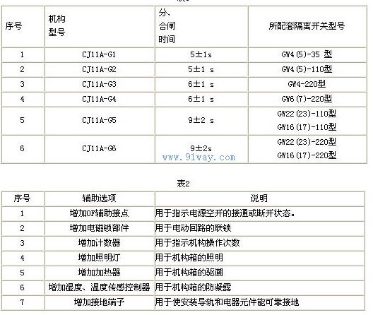
Working principle and structure
The CJ11A mechanism is driven by an electric motor and transmits torque to the output shaft through gears, worm gears, and worm gears. During installation, it is connected to an isolation switch through a steel pipe for opening and closing. It mainly consists of an electric motor, a mechanical reduction transmission system, an electrical control system, and a casing.
The electric motor is a three-phase AC asynchronous motor, and the electrical control system includes automatic switches, remote/stop/local switching switches, manual electric interlocking devices, opening and closing buttons, contactors, travel switches, etc.
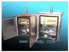
The box is made of steel plate or stainless steel plate to provide support and protection. For ease of installation and maintenance, one door is opened on the front and one door is opened on the side.
6.1 The operating procedure for CJ11A mechanism is as follows:
6.1.1 Electric operation
Pull the local remote control switch to the appropriate position and close the power switch to turn on the power. When opening the circuit, press the opening button to turn on the control coil of the opening contactor, which connects the motor circuit. The motor drives the deceleration device and drives the isolation switch and grounding switch connected to the main shaft to achieve opening. When the spindle approaches the end position of the circuit breaker, the limit switch will act to cut off the power supply to the control coil of the circuit breaker contactor, reset the circuit breaker contactor, cut off the power supply to the motor, and the mechanical limit device will limit the mechanism to the accurate position of the circuit breaker.
When closing, press the closing button, and the electric motor drives the deceleration device to drive the isolation switch and grounding switch connected to the spindle to achieve closing. Its operating principle is the same as opening.
During the opening and closing process, if there is a need to stop halfway or if there is an abnormal situation, the control power can be cut off by pressing the stop button. The lower part of the main shaft of the mechanism is equipped with 8 pairs of auxiliary switches (4 normally open, 4 normally closed) for interlocking and signal indication.
This institution is suitable for remote control system devices, realizing remote control, and can also be operated locally in front of the electric motor mechanism, for which remote/stop/local switches are provided. When the mechanism is adjusted or repaired, it can be pulled to the local position and operated in front of the mechanism (at this time, the remote control circuit has been cut off). When pulled to the remote control position, the mechanism opening and closing buttons do not work and can only be remotely controlled.
The mechanism equipped with a heater, when it is necessary to increase the temperature inside the box to dispel humid air and prevent electrical components from getting damp, can close the heater switch and put the heater into operation. Turn on the heater switch after completing the work.
6.1.2 Manual operation of opening and closing switches
Open the side door, and the travel switch on the side door will cut off the power supply of the control circuit. The electric operation will not work. Simply insert the handle into the worm shaft to perform the opening and closing operation.
7. Installation and adjustment
7.1 Preparation before installation
7.1.2 After unpacking, check whether the appearance of the mechanism is complete and whether the nameplate data matches the order.
7.1.3 After cleaning the inside and outside of the mechanism, use the handle to manually open and close it several times to check if the mechanism operates normally.
7.2 Install the mechanism on the base frame, do not tighten the installation bolts temporarily, use a lead hammer to align the center, and make the output shaft of the mechanism
Concentric with the isolation switch shaft, then tighten the installation bolts.
7.3 Connect the mechanism and isolation switch according to the isolation switch manual.
Before powering on, the mechanism should be in the middle position of opening and closing, and the setting current of the thermal relay should be 1.6A
Then turn on the power, press the open or close button, and observe whether the spindle rotation direction is correct. If the direction is opposite, immediately cut off the power and change the motor wiring. After rotating in the correct direction, the secondary circuit electrical interlocking signal is correct and the relevant connection parts are not loose. The mechanical transmission part is stable and normal. The adjustment work is now complete.
8. Use and maintenance
8.1 Under normal operation, the product should be regularly inspected according to the actual situation. Specifically, as follows:
8.1.2 Use the handle to operate and check whether each transmission section is flexible and whether the auxiliary switch is switching normally.
8.1.3 Check if all fasteners are loose and if any spare parts are damaged.
8.1.4 Check whether the secondary circuit wires and electrical components are damaged and whether the contact is good.
After inspection, it was confirmed that all parts of the organization were normal. Apply lubricating grease to the rotating friction part, and after several electric cycles without any abnormalities, it can be put into normal operation.
9. Packaging, transportation, and storage
The packaging method is wooden crate, and the mechanism body, accompanying accessories, and documents (product certificate, user manual) are all packaged in one wooden crate. If the product is not installed immediately after arriving at the destination, it must be placed in a rainproof, dry, and ventilated place. If it is stored for a long time, it should be checked regularly.
10. Complete supply
One CJ11A motor operating mechanism; One operating handle; 1 key for opening the box; 1 coupler and 1 pin each.
11. Ordering Notice
When placing an order, the following information should be provided: mechanism model, motor voltage and control voltage, number of auxiliary poles, etc.
Home|Quality Commitment|Ordering|Payment method|product delivery|support|Disclaimer|Contact Us
Copyright®2011 www.91way.com Copyright.
Phone:+86-21-66770508 +86-13916500500 Fax:+86-21-66108310
Email:91way@163.com Wechat:40606422
沪ICP备2021005791号 ![]() 沪公网安备31010702003255号
沪公网安备31010702003255号