
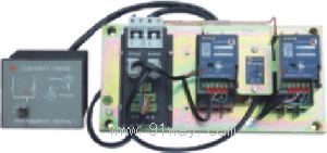
| Product name: | CA1 series dual power conversion switch | ||||||
| specification: |  |
||||||
| Category: | low-voltage electrical apparatus -- dual power switch | ||||||
| Price: | factory price | ||||||
| Brand: | |||||||
| Place of Origin: | China | ||||||
| Available Quantity: | batch | ||||||
| delivery cycle: | Spot goods (or inquire by telephone) | ||||||
|
|||||||
|
model |
CA1 | ||||||||
|
controller type |
Electronic type |
Intelligent type (intelligent communicable type) | |||||||
|
Converter model |
W-shaped |
Q-type |
|||||||
|
Main performance |
Detect the voltage of either phase of the commonly used or backup power supply. If the detected phase voltage drops below 30% of the rated control power supply voltage, there is a phase loss, or the power supply is cut off, action will be taken. |
Detect the voltage of each phase of the commonly used power supply and any phase voltage of the backup power supply. If the detected phase experiences overvoltage, undervoltage, phase loss, or power outage, the action will be taken. |
Detect the voltage of each phase of the commonly used power supply and the A-phase voltage of the backup (or power generation) power supply. If the detected phase experiences overvoltage, undervoltage, phase loss, or power outage, take action. | ||||||
|
Four position working status |
a. Automatic operation | ||||||||
|
b. Mandatory use of "common" power sources (or grid power sources) | |||||||||
|
c. Mandatory backup power source (or power generation source) | |||||||||
|
d. Stop (all closed) | |||||||||
|
Automatic controller status indication |
Closing, opening, and fault tripping | ||||||||
|
Undervoltage |
50% to 90% rated voltage, user adjustable |
65%, 75%, 85% rated voltage, user adjustable | |||||||
|
overvoltage |
105% to 120% rated voltage, adjustable by the manufacturer |
115% rated voltage | |||||||
|
control function |
R-type |
S-type |
Fire linkage type |
F-type |
R-type |
S-type |
F-type | ||
|
Self switching and self recovery in the common backup room |
The automatic switching and non recovery of the common backup room |
Optional R/S type |
Self switching and self recovery between commonly used power sources |
Self switching and reuse between common and backup rooms |
Self switching between common and backup rooms without reuse |
Self switching and reuse between commonly used power generation sources | |||
|
Control characteristics* |
T1 and t3 are user adjustable |
T1, t2, t3, t4, t5, t6 user adjustable |
T1, t2, t3, t4 are user adjustable |
T1, t2, t3, t4, t5, t6 user adjustable | |||||
|
common power supply |
backup power supply |
control function |
|
normal |
normal |
Common power supply: Q1 on, Q2 off |
|
abnormal |
normal |
After t1 delay, Q1 is divided, and after t2 delay, Q2 is closed - backup power supply |
|
return to normal |
normal |
After a delay of t3, Q2 is divided, and after a delay of t4, Q1 is closed - restoring normal power supply |
|
common power supply |
Backup power supply |
control function |
|
normal |
normal |
Common power supply: Q1 on, Q2 off |
|
abnormal |
normal |
After t1 delay, Q1 is divided, and after t2 delay, Q2 is closed - backup power supply |
|
return to normal |
normal |
Still powered by backup power supply |
|
normal |
Abnormal |
After a delay of t3, Q2 is divided, and after a delay of t4, Q1 is closed - powered by a common power supply |
|
Grid power supply |
Power generation source |
control function |
|
normal |
No power generation |
Grid power supply: Q1 on, Q2 off |
|
abnormal |
No power generation |
Delayed issuance of power generation command t5, waiting for power generation |
|
abnormal |
normal |
After a delay of t1, Q1 is divided and an unloading instruction is issued. After a delay of t2, Q2 is closed - the power supply is used for power generation |
|
return to normal |
normal |
After the stable time of the power grid reaches the t6 setting value, a command to stop power generation is issued. After a delay of t3, Q2 is divided, and then after a delay of t4, Q1 is closed - automatically returning to the power grid for power supply |
|
model |
Rated control power supply voltage Us (V) |
Conversion disconnection delay time t1 (s) |
Switching on delay time t2 (s) |
Return disconnect delay time t3 (s) |
Return the connection delay time t4 (s) |
Power generation instruction delay time t5 (s) |
Delay time t6 (s) for power generation shutdown command |
|
CA1R |
AC230 |
0.5-64 user adjustable |
zero point five |
0.5-64 user adjustable |
zero point five |
―― |
―― |
|
CA1F |
AC230 |
0.5-64 user adjustable |
0.5-64 user adjustable |
0.5-64 user adjustable |
0.5-64 user adjustable |
1-180 users adjustable |
32 to 600 users adjustable |
|
model |
Circuit breaker executed |
Number of poles and short-circuit breaking capacity level of circuit breaker |
rated current |
Rated working voltage |
Rated insulation voltage |
rated frequency |
|
CA1-63 |
CM1-63 |
Three poles (L, M) |
(6) 10, 16, 20, 25, 32, 40, 50, 63 |
400V |
500V |
50Hz |
|
CA1-100 |
CM1-100 |
Three poles (C, L, M, H) |
(10) 16, 20, 25, 32, 40, 50, 63, 80, 100 | |||
|
CA1-160 |
CM1-160 |
Three poles (C, L, M, H) |
100, 125, 140, 160 | |||
|
CA1-225 |
CM1-225 |
Three poles (C, L, M, H) |
100, 125, 140, 160, 180, 200, 225 | |||
|
CA1-400 |
CM1-400 |
Three poles (C, L, M, H) |
225, 250, 315, 350, 400 | |||
|
CA1-630 |
CM1-630 |
Three poles (C, L, M, H) |
400, 500, 630 | |||
|
CA1-800 |
CM1-800 |
Three poles (M, H) |
630, 700, 800 |
CA1 series dual power conversion switch
Home|Quality Commitment|Ordering|Payment method|product delivery|support|Disclaimer|Contact Us
Copyright®2011 www.91way.com Copyright.
Phone:+86-21-66770508 +86-13916500500 Fax:+86-21-66108310
Email:91way@163.com Wechat:40606422
沪ICP备2021005791号 ![]() 沪公网安备31010702003255号
沪公网安备31010702003255号