CGFK intelligent low-voltage composite switch is the latest generation of reactive power compensation capacitor switching device, which is an intelligent control execution component and the latest scientific research achievement of our company. This product has significant technical advantages over switching components such as AC contactors, thyristors, or solid-state relays. The main advantage is that after receiving external control signals, the optimal input (cut-off) point can be automatically found through logical judgment. Ensure zero crossing switching and no surge current; Contact points are not sintered; Low energy consumption; No harmonic generation; At the same time, it has voltage anomaly protection. Compared with similar products, this kind of compound switch developed by our company has great progressiveness in technology, especially in safety and reliability. At present, it has passed the test of reactive power compensation set by the Ministry of Power Industry? lt;BR>
Main technical features
This product adopts intelligent control technology and the latest electronic components, suitable for on/off control of AC 380V reactive power compensation capacitors. The basic working principle is to connect the thyristor in parallel with the magnetic holding relay, so that the composite switch has the advantages of thyristor zero crossing switching at the moment of connection and disconnection, and the contactor has the advantage of no power consumption during normal connection. The product mainly has the following technical features: zero crossing switching; The basic working principle of a composite switch is to connect a thyristor switch in parallel with a magnetic holding relay to achieve voltage zero crossing conduction and current zero crossing cutoff, so that the composite switch has the advantages of a thyristor switch at the moment of connection and disconnection, and has the advantage of no power consumption of a contactor switch during normal connection. The implementation method is: when put into operation, the thyristor first crosses the zero contact at the moment of voltage zero crossing, and then the magnetic holding relay is closed and turned on after stabilizing; When cutting out, the magnetic holding relay is first disconnected, and the thyristor delays the zero crossing to disconnect, thereby achieving current zero crossing cut-off.
By using a microcontroller to control switching and intelligently monitor the operation status of thyristors, magnetic holding relays, input power supplies, and loads, it has comprehensive protection functions.
Voltage fault phase loss protection: When the system is supplied with voltage phase loss, the switch refuses to close; If there is a phase loss after connection, it will automatically shut down;
Power voltage phase loss protection: When the working power supply is in phase loss, the switch refuses to close; If there is a phase loss after connection, it will automatically shut down;
Self diagnostic fault protection: The system automatically monitors the operation status of the thyristor and magnetic holding relay. If it fails, it will refuse to close or automatically trip and disconnect;
Power outage protection: In case of sudden power outage after connection, it will automatically trip and disconnect;
No harmonic injection: Due to the fact that the conduction moment is triggered by the zero crossing of the thyristor, the relay will engage and conduct after a delay, and the relay will engage and conduct without generating harmonics.
Low power consumption: Due to the use of magnetic holding relays, the control device only consumes power at the moment of switching action, and does not consume power normally; And due to the low contact resistance of the magnetic holding relay, it does not generate heat, so there is no need to add heat sinks or fans, which reduces costs. Completely avoiding the burning phenomenon of thyristors, while also not causing harm to other electrical appliances running on the same machine, truly achieving the goal of energy conservation and consumption reduction.
Main technical parameters
| Rated working voltage |
380V,220V/AC±20% |
rated frequency |
50Hz±5 |
| working power supply |
220V |
rated current |
45/55A |
| service life |
100,000 times |
phase number |
Three phase (delta connection), single-phase (Y-shaped connection) |
| Control capacity |
≤25/30K Var |
Circuit power consumption |
≤1.5VA |
| Contact voltage reduction |
≤100mV |
Contact voltage withstand |
≥1600V |
| response time |
≤1000ms |
on-resistance |
≤0.003Ω |
| Overall dimensions |
112×172×123mm |
|
|
| Interval between each connection and disconnection |
≥ 1 second |
| Interval between two consecutive connections |
≥ 120 seconds |
| starting voltage |
DC 4-23V, input impedance: ≥ 6.8K |
| Security protection function |
Voltage fault phase loss protection |
When the system voltage is supplied with phase loss power, the switch refuses to close; If there is a phase loss after connection, it will automatically shut down |
| Power supply voltage phase loss protection |
When the working power supply lacks phase power, the switch refuses to close; If there is a phase loss after connection, it will automatically shut down |
| Self diagnostic fault protection |
The system automatically monitors the operating status of thyristors and magnetic holding relays. If they fail, they refuse to close or automatically trip and disconnect |
| Power outage protection |
When there is a sudden power outage after connection, it will automatically trip and disconnect |
| insulation class |
Under normal atmospheric conditions, ≥ 10M Ω |
Installation and operation methods
Installation position and size
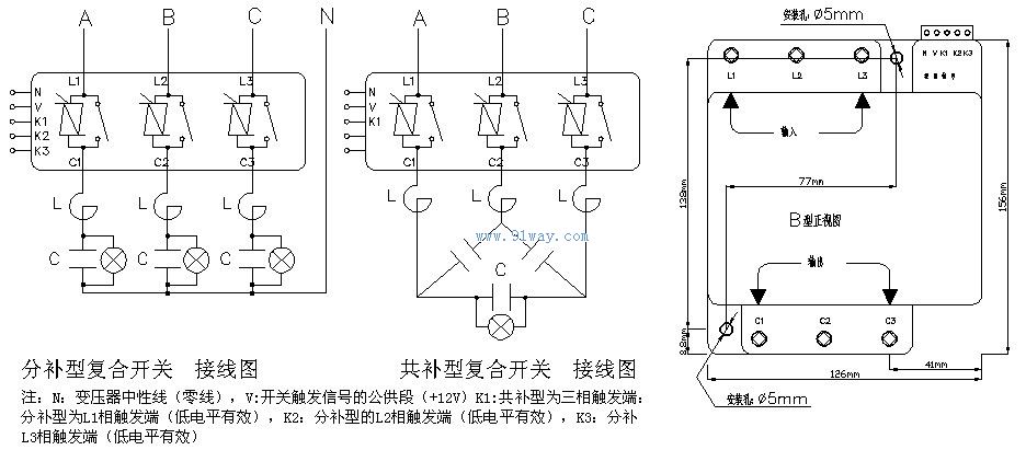
This device is installed on a 380V three-phase four wire distribution network and is used for on/off control of low-voltage reactive power compensation capacitors. Users can install it in the low-voltage reactive power compensation capacitor cabinet or other appropriate locations. Generally, a hanging installation method is used. Please refer to the wiring diagram shown below.
Composite switch selection table
|
Order model |
Capacity of the capacitor group |
Compensation method |
|
|
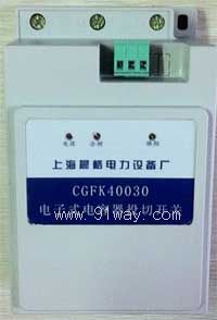
CGFK40030 |
5-30Kvar |
jointly supplement |
|
|
CGFK25030 |
30Kvar |
Split compensation (10Kvar per phase) |
|