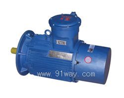
YB2EJ series electromagnetic brake explosion-proof three-phase asynchronous motor
1、 Overview
Since its first use in ports in 1904, Quick Release Mooring Hooks have been widely used in ports in Europe, America, and other countries due to their advantages of safety, flexibility, labor-saving, and speed. With the construction and renovation of modern docks in China, the rapid detachment device has become a development trend to replace old-fashioned mooring bollards.
In order to provide a safe, reliable, and user-friendly power for the rapid cable removal device, Jiangsu Dazhong Electric Machinery Co., Ltd. and Lianyungang Beilite Technology Development Co., Ltd. jointly developed the YB2EJ series electromagnetic brake explosion-proof three-phase asynchronous motor, and also provided the non explosion-proof Y2EJ series electromagnetic brake three-phase asynchronous motor.
The electromagnetic brake motor (explosion-proof and non explosion-proof) used for the rapid cable detachment device adopts AC brake, and both the motor and brake use S2 workpiece system with a continuous working time of 60 minutes. Due to the absence of rectification devices and cooling fans, it has the characteristics of compact structure, high protection level and explosion-proof level, and easy use and maintenance.
The YB2EJ series electromagnetic brake explosion-proof three-phase asynchronous motors (frame H132~H160) are 4P-5.5KW, 4P-7.5KW, and 4P-11KW, respectively, which comply with the requirements of GB3836.1-200 "Electrical Equipment for Explosive Gas Environments Part 1: General Requirements" and GB3836.1-200 "Electrical Equipment for Explosive Gas Environments Part 2: Explosion proof Type" d ". The explosion-proof mark is dxd Ⅱ BT4.
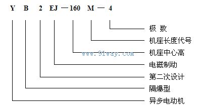
2、 Product model and name
The meaning of explosion-proof motor model:
3、 Scope and conditions of use
1. The YB2EJ series electromagnetic brake explosion-proof three-phase asynchronous motor is suitable for common combustible gases, vapor levels, and temperature levels, as shown in Table 1.
|
level |
Group |
|
T1 |
T2 |
T3 |
T4 |
|
ⅡA |
Methane, ethane, propane, phenylethane, toluene, xylene, carbon monoxide, acetic acid |
Butane, propane, ethylbenzene
Methanol, ethanol, propanol, butanol |
Butane, ethane, heptane, octane, decane, cyclohexane, kerosene, diesel, gasoline |
|
|
ⅡB |
Propane, cyclopropane, coke oven gas |
Ethylene 1.3-butadiene epoxyethane, ethane, 1.2-epoxypropane |
Dimethyl ether, acrolein, methylfurfuryl alcohol, tetrahydrofuran, hydrogen sulfide |
Ethyl methyl ether, diethyl ether, tetrafluoroethylene |
2. Usage conditions
2.1 The ambient air temperature varies with the season, but does not exceed 40 ℃, with a minimum ambient air temperature of -15 ℃.
2.2 The altitude shall not exceed 1000m. The maximum relative humidity of the ambient air shall not exceed 95%, and the average minimum temperature of the month shall not exceed 25 ℃.
2.3 The rated voltage is 380V.
The rating of the 2.4 motor is based on the short-term working system (S2, 60 minutes).
The motor adopts F-class insulation, and the temperature rise of the stator winding (resistance method) is assessed at 85K.
4、 Main specifications and installation structure of electric motors
1. The main specifications of this series of motors are shown in Table 2.
|
frame size |
Synchronous speed r/min |
Rated power KW |
|
90L |
one thousand and five hundred |
one point five |
|
100L1 |
one thousand and five hundred |
two point two |
|
100L2 |
one thousand and five hundred |
three |
|
112M |
one thousand and five hundred |
four |
|
132S |
one thousand and five hundred |
five point five |
|
132M |
one thousand and five hundred |
seven point five |
|
160M |
one thousand and five hundred |
eleven |
2. The structure and installation type of this series of motors are shown in Table 3.
|
frame size |
Structure and Installation Code (M) |
|
90~160 |
B3、B5、B6、B7、B8、V1、V3、V5、V6 |
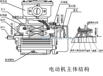
5、 Main Structure Overview
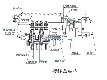
1. The junction box of the series motor is located at the top of the motor, and can also be wired on the left or right side of the motor. It is suitable for rubber sheathed wire (or plastic cable) structures. This series motor has 6 wiring terminals, including a grounding terminal, and is made into one outlet according to its specifications.
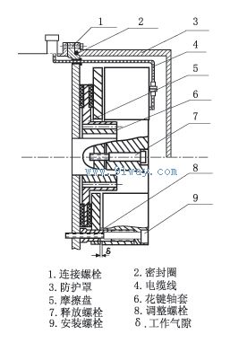
2. The main structure of this series of motors is shown in Figure 1, the junction box structure is shown in Figure 2, and the brake structure is shown in Figure 5.
3. This series of motors adopts the △ connection method. (Internally connected at the factory)
4. The matching data of this series of motors and brakes are shown in Table 4.
|
YB2EJ motor data |
Exchange brake data |
|
frame size |
rated power
(KW) |
rated voltage
(V) |
Customized power torque M (N ・ m) |
Maximum allowable working air gap δ (mm) |
Idle braking time
(ms) |
|
ninety |
one point five |
three hundred and eighty |
fifteen |
one |
fifty |
|
one hundred |
2.2-3.0 |
three hundred and eighty |
thirty |
one |
fifty |
|
one hundred and twelve |
four |
three hundred and eighty |
forty |
one |
fifty |
|
one hundred and thirty-two |
5.5~7.5 |
three hundred and eighty |
eighty |
one point two |
fifty |
|
one hundred and sixty |
11~18.5 |
three hundred and eighty |
one hundred and fifty |
one point two |
fifty |
6、 Explosion proof points
1. This series of motors are explosion-proof motors, and it is required that when the explosive mixture inside the motor explodes, the explosion-proof shell should not be damaged or deform to affect the explosion-proof performance; Internal explosive flames are not allowed to cause external explosive mixtures to explode through the explosion-proof joint surface of the shell. Therefore:
A、 The components that make up the explosion-proof shell, such as the machine base, end cover, bearing inner cover, junction box cover, junction box seat cover, etc., must undergo a 1.0Mpa water pressure test after precision machining for 10-12 seconds to pass.
B、 The length, gap, surface roughness, electrical gap and creepage distance between exposed conductors inside the junction box and between exposed conductors and metal shells of the explosion-proof joint surface are shown in Figures 1 and 2.
C、 The bolts connecting the explosion-proof shell are equipped with spring washers to prevent them from loosening on their own.
D、 The machine base, end cover, bearing inner cover, junction box cover, junction box cover, cover, wiring bolts, terminal sleeves (or wiring boards), shaft, and sealing ring are explosion-proof components.
2. Under rated working conditions, the surface temperature of the motor casing shall not exceed the temperature specified in Table 5, and the temperature at the inlet shall not exceed the allowable temperature of the cable used (70 ℃) to ensure that the cable can operate smoothly.
Table 5:
|
Explosive mixture level |
T1 |
T2 |
T3 |
T4 |
|
The maximum allowable temperature on the surface of the motor is 0 ℃ |
four hundred and forty |
two hundred and ninety |
one hundred and ninety-five |
one hundred and thirty |
7、 Installation and use
1. Preparation before installation
1.1 When opening the motor box, check whether the packaging box is intact and undamaged.
After opening the box, the motor should be carefully cleaned of dust and rust proof coating.
Before installing the electric motor, the following inspections should be carried out. If it does not meet the requirements, it is not allowed to be put into use.
A、 There is an explosion-proof mark and explosion-proof qualification number, which are consistent with the requirements of the motor's usage scenario.
B、 The components of the explosion-proof shell are connected correctly and sturdy.
C、 All explosion-proof parts should be free of cracks and defects that affect explosion-proof performance (new motors that have not been disassembled need not be inspected).
D、 The bearing grease and oil injection and discharge device are unobstructed.
E、 Insulation resistance between stator winding and casing: not less than 0.38M Ω at rated voltage of 380V.
2. The connection between the motor shaft extension and the coupling should pay attention to the appropriate fitting accuracy, otherwise it may cause bearing noise and vibration.
3. Connection between electric motor and power cable
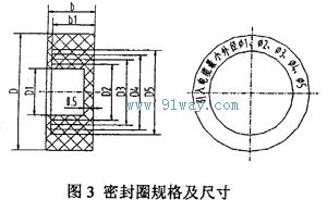
3.1 The outer diameter of the power cable should match the aperture of the sealing ring, which is made of rubber XH-21. The specifications and dimensions are shown in Figure 3 (the concentric circles of the sealing ring can be peeled off according to the outer diameter of the incoming cable). The diameter difference should not exceed 1mm. When pressing the wire bucket, it should be ensured that there is no gap between the sealing ring and the cable, and between the sealing ring and the junction box seat, otherwise the explosion-proof performance will be lost.
3.2 The introduced cable core wire should be connected between two bow shaped washers, and attention should be paid not to protrude the flying spikes of the core wire. The introduced cable should also be tightly fixed with wiring clamps and bow shaped washers to prevent movement.
There are six terminals inside the junction box, U1, V1, W1 (brake power terminal), U2, V2, W2 (motor power terminal). When powered by a non variable frequency power supply, the power supply can be directly connected to U1, V1, W1 or U2, V2, W2. If the motor needs to be connected to a variable frequency power supply, the connecting pieces on U1, V1, W1, U2, V2, and W2 must be removed. Provide separate power supply for the motor and brake. (The brake must not be connected to a variable frequency power supply)
3.4 The phase sequence U, V, and W of the motor must correspond to the phase sequence A, B, and C connected to the external power supply. The direction of rotation of the motor should be clockwise when viewed from the shaft extension end, otherwise the motor will reverse,
See Table 6.
|
phase sequence |
A |
B |
C |
|
head |
U2 |
V2 |
W2 |
3.5 The internal and external grounding bolts should be able to be grounded.
After the wiring of the motor is checked and confirmed to be correct, the power supply can be connected for no-load trial operation, and the motor should be observed for any abnormal phenomena. After normal idling, it can be put into load operation.
After the cable sealing ring of the 3.7 introduction device ages and deteriorates, it should be replaced in a timely manner. The size is shown in Figure 3, and the minimum outer diameter of the cable used by the user is shown in the table.
8、 Maintenance and Repair
1. The motor should be regularly inspected and cleaned, and the casing should not accumulate dust. It is not allowed to use a faucet to spray and clean the motor.
2. The allowable temperature of the bearings during the operation of the electric motor shall not exceed 95 ℃ (thermometer method). The bearings shall be inspected at least once every 2500 hours (about half a year). If the bearing lubricating grease is found to have deteriorated, it shall be replaced in a timely manner. Before replacement, the waste oil in the bearing cover, oil storage box, and the oil pipes and cups of the oil injection and discharge device shall be cleaned, and the bearings shall be cleaned with gasoline. The lubricating grease shall be lithium based grease No. 3 (GB7324-87), with 2/3 for 4-pole and above. The bearing grades are shown in Table 7.
3. When disassembling and assembling the electric motor, attention should be paid to protecting the explosion-proof surface. Motors with machine base numbers (H80~160) do not have bearing inner and outer covers. The bearing * is installed in the bearing chamber of the end cover and locked axially with a retaining ring. When disassembling the electric motor, the V-shaped shaft seal ring at the shaft extension end should be removed first, the front end cover should be removed, and then the cover of the brake end and the fixing bolts of the rear end cover should be removed. The rear end cover and the rotor should be pulled out from the brake end together. First, lower the brake, and then remove the rear end cover and the bearing hole with the retaining ring from the rotor. Remove the hole with the retaining ring to remove the bearing. When assembling the electric motor, first install the bearing into the bearing chamber of the rear end cover, then insert the hole into the end cover groove with a retaining ring, fit it onto the rotor, fix the rear end cover, and then install the shaft extension end bearing wave spring plate. The front end cover should be fixed with bolts, install the V-shaped shaft seal ring, and then install the brake (① Before installing the brake, remove debris and oil stains. This brake belongs to the dry type and should work in an oil-free state to avoid affecting the braking torque; ② When installing the brake, adjust the installation screw to the specified working air gap δ value, and then unscrew the hollow bolt to tighten the rear end cover of the motor. )Once the cover is installed, the motor assembly is complete. During assembly, the explosion-proof surface needs to be coated with 204-1 anti rust grease.
4. When the motor is damp, it should be dried, and drying or short-circuit current method can be used. During the drying process, the temperature rise of the winding should gradually increase and should not exceed 155 ℃. When using the short-circuit current method for drying, the motor is in a short-circuit state, and its input current should be 0.6~0.8 times the rated current value. Motors that are severely damp should not be dried with direct current to avoid electrolysis.
5. When replacing the winding, it is necessary to record the type and size of the original winding, as well as the number of turns and wire gauge. When these data are lost, they should be requested from the manufacturer. Changing the original design winding at will will deteriorate one or several performance aspects of the motor, making it unusable.
6. Replace the brake friction disc or brake: ① The friction disc system is easy to replace. When the friction material surface wears down to the level of the metal disc core, the friction disc should be replaced. The operation sequence is as follows: remove the protective cover, separate the cable socket from the brake, loosen the installation bolt to remove the brake, remove the friction disc in the direction of the spline teeth, replace with a new friction disc, and reinstall according to the installation sequence. ② If the brake needs to be replaced, the operation sequence is the same as above. ③ In the absence of power, if it is necessary to rotate and adjust the transmission system, manual release can be used. The operation sequence is: remove the protective cover, tighten the release bolts (two) until the motor shaft can be rotated by hand. After adjustment, please loosen (turn left) the two release bolts again, otherwise the brake will lose its braking function.
Figure 3 Sealing ring specifications and dimensions:
|
frame size |
wiring method |
D1 |
Φ1 |
D2 |
Φ2 |
D3 |
Φ3 |
D4 |
Φ4 |
D5 |
Φ5 |
D |
B1 |
B2 |
|
H90-132 |
rubber-sheathed cable |
Φ14 |
Φ13 |
Φ20 |
Φ19 |
Φ25 |
Φ24 |
|
|
|
|
Φ42 0 -0.62 |
eighteen |
nineteen |
|
H160 |
Φ14 |
Φ13 |
Φ20 |
Φ19 |
Φ26 |
Φ25 |
Φ31 |
Φ30 |
Φ35 |
Φ34 |
Φ58 0 -0.74 |
twenty-four |
twenty-six |
Table 7:
|
frame size |
polar number |
Axis extension end |
Non axial extension end |
|
ninety |
4P |
one hundred and eighty thousand two hundred and five |
one hundred and eighty thousand two hundred and five |
|
one hundred |
4P |
one hundred and eighty thousand two hundred and six |
one hundred and eighty thousand two hundred and six |
|
one hundred and twelve |
4P |
one hundred and eighty thousand two hundred and six |
one hundred and eighty thousand two hundred and six |
|
one hundred and thirty-two |
4P |
one hundred and eighty thousand two hundred and eight |
one hundred and eighty thousand two hundred and eight |
|
one hundred and sixty |
4P |
one hundred and eighty thousand three hundred and nine |
one hundred and eighty thousand two hundred and nine |
be careful:
1. It is strictly prohibited to open the junction box cover with electricity!
2. Do not change the circuit and electrical parameters related to the circuit of the explosion-proof motor; Do not change the specifications, models, and explosion-proof structures of electrical components!
3. When installing gears or couplings, if the fit is too tight and the hammer strike is too heavy, it will damage the bearings and cause abnormal noise!