
| Product name: | JKL5 series intelligent reactive power automatic compensation controller | ||||||
| specification: |  |
||||||
| Category: | low-voltage electrical apparatus -- Compensation equipment | ||||||
| Price: | factory price | ||||||
| Brand: | Shanghai | ||||||
| Place of Origin: | China | ||||||
| Available Quantity: | batch | ||||||
| delivery cycle: | Spot goods (or inquire by telephone) | ||||||
|
|||||||
1、 Overview
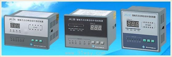
The JKL5 series intelligent reactive power automatic compensation controller is a dedicated controller for compensating reactive power in low-voltage distribution systems, which can be used in conjunction with models of low-voltage electrostatic capacitance screens. JKL5A type (with an opening size of 162 × 102mm). JKL5B type (with an opening size of 140 × 102mm) and JKL5C type (with an opening size of 113 × 113mm, the same as the 42L6 instrument) have five specifications of output channels: 4, 6, 8, 10, and 12. This machine adopts advanced technologies from both domestic and foreign sources, and has outstanding advantages such as small size, light weight, complete functions, strong anti-interference ability, stable and reliable operation, and precise compensation. Designed according to the latest national professional standards JB and T9663-1999, and inspected by the National Quality Supervision and Inspection Center for Electric Control and Distribution Equipment, the type test is qualified
2、 Usage conditions
1. Altitude not exceeding 1000M
2. The ambient temperature shall not exceed+40 ℃, the average temperature within 24 hours shall not exceed+35 ℃, and the minimum ambient temperature shall not be lower than -10 ℃.
3. The relative temperature of the air should not exceed 85% (at 25 ℃).
4. The surrounding environment is free of flammable and explosive media, and there is no presence of conductive dust or corrosive gases.
5. The voltage fluctuation range of the power grid shall not exceed ± 10% of the rated voltage of the machine.
3、 Functional Features
1. Adopting more advanced international chips and adding power-off memory function. When the power supply of the compensator is cut off, the parameters and programs are automatically memorized and never lost; When re powering, the compensator still operates and controls according to the parameters and programs set by the original user;
2. LED digital display of power factor of the power grid, display range: lag (0.00~0.99), lead (0.00~0.99).
3. The three function setting keys on the panel keyboard can be used to set the numerical display COS φ setting value, delay setting value, and overvoltage setting value. Concise human-machine dialogue makes operation extremely convenient.
4. When the voltage of the power grid exceeds the local overvoltage setting value, the digital COS φ meter automatically converts and displays the current voltage value of the power grid, and automatically cuts off the capacitor banks that have been put into operation step by step.
5. Distinguish the polarity of the sampled current (i.e. automatically identify the polarity) and automatically switch. Bringing great convenience to installation, debugging, and use.
6. When the sampling signal line is open or there is no input sampling current signal, the local digital COS φ automatically displays 0. CC.
7. The output action program adopts a cyclic working mode of first connected, first disconnected, and first connected, as well as encoding working modes of 1, 2, 2, 2, 2, and 1 that are suitable for the action program requirements of the local compensation device.
8. It has manual/automatic conversion. When set to automatic mode, the machine automatically tracks the power factor and reactive current of the power grid, controls the automatic input or output of capacitors, and can achieve manual input or output on the machine when set to manual mode.
There are LED indicators for leading, lagging, overvoltage, and undercurrent. LED prompts for programming input.
10. Strong anti-interference ability, able to withstand interference pulses of 2000V directly input from the power grid, higher than national professional standards.
4、 Main specifications and technical parameters
1. The JKL5 series intelligent reactive power automatic compensation controller has the following specific model specifications (see table below)
|
model |
Output points |
Controllable number of capacitor groups |
respective notes |
|
JKL5A/B/C |
four |
four |
|
|
six |
six |
||
|
eight |
eight | ||
|
ten |
ten | ||
|
twelve |
twelve | ||
|
Users can choose to place orders |
For example: JKL5C-10 |
12 units | |
2. Compensator setting value and adjustable range:
|
Power factor COS φ value 0.97 |
0.70-0.98 continuous digital setting |
|
Overvoltage protection value 430V |
440-440V five level continuous digital setting |
|
Each switching delay is 30 seconds |
-90S continuous digital setting |
|
Ensure the current value of the sampling transformer during automatic switching: lower limit ≥ 150mA, upper limit ≤ 5A | |
3. Basic parameters:
|
Rated working voltage |
UBC phase, AC 50Hz 380V ± 10% |
|
current sampling |
Phase A Ⅰ A AC 0-5A |
|
Output touch capacity point capacity |
AC 220V × 5A or 380V × 3A |
|
dielectric strength |
Exchange 3000V |
|
working system |
continuous work system |
|
weight |
About 1.0 kilogram |
Installation method
The installation of the JKL5 series is an embedded shell structure with mounting holes on the side. The hooks for fastening accessories are inserted into the holes, and the controller is fixed to the screen by turning the screws on the accessories.
1. The external dimensions of JKL5A model are 170 × 110 × 127mm, with an installation opening of 162 × 102mm (width × height) and an embedded depth of 127mm
2. The external dimensions of JKL5B model are 147 × 110 × 127mm, with installation openings of 140 × 102mm (width × height) and an embedded depth of 127mm
3. The JKL5C model adopts the 42L6 series instrument structure, with external dimensions of 120 × 120 × 80mm, installation openings of 113 × 113mm, and an embedded depth of 80mm
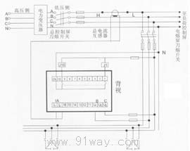
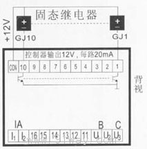
Wiring method
1. Controller voltages U1 and U2 are connected to phases B and C. (See Figure 1 and Figure 2)
2. The sampling current terminals I1 and I2 must be taken from the secondary of the A-phase current transformer of the total load (main cabinet), and must not be taken from the capacitor screen.
3. COM serves as the common source for the 1-10 sets of internal relays at the controller output terminal, and the voltage of the J coil of the AC contactor is 220V.
JKL5 series intelligent reactive power automatic compensation controller
Home|Quality Commitment|Ordering|Payment method|product delivery|support|Disclaimer|Contact Us
Copyright®2011 www.91way.com Copyright.
Phone:+86-21-66770508 +86-13916500500 Fax:+86-21-66108310
Email:91way@163.com Wechat:40606422
沪ICP备2021005791号 ![]() 沪公网安备31010702003255号
沪公网安备31010702003255号