
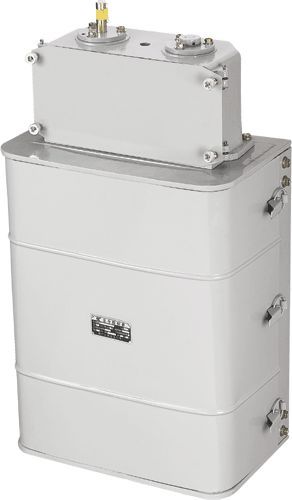
| Product name: | LK4 series master controller | ||||||
| specification: |  |
||||||
| Category: | low-voltage electrical apparatus -- Master controller | ||||||
| Price: | factory price | ||||||
| Brand: | Shanghai | ||||||
| Place of Origin: | China | ||||||
| Available Quantity: | batch | ||||||
| delivery cycle: | Spot goods (or inquire by telephone) | ||||||
|
|||||||
|
model |
Total number of circuits |
Number of cam discs on each axis |
Cam assembly rotation method |
Gearbox transmission ratio |
|
LK4-024 |
two |
two |
―― | |
|
LK4-044 |
four |
four |
―― | |
|
LK4-054 |
six |
six |
―― | |
|
LK4-028-1 |
two |
two |
1:30 | |
|
LK4-028-2 |
two |
two |
1:5 | |
|
LK4-048-1 |
four |
four |
1:30 | |
|
LK4-048-2 |
four |
four |
1:5 | |
|
LK4-058-1 |
six |
six |
1:30 | |
|
LK4-058-2 |
six |
six |
1:5 | |
|
LK4-148/3 |
eight |
four |
series connection |
1:16.65 |
|
LK4-148/4 |
eight |
four |
parallel connection |
1: 1:20 or 1:36 |
|
LK4-168/3 |
sixteen |
eight |
series connection |
1:16.65 |
|
LK4-168/4 |
sixteen |
eight |
parallel connection |
1: 1:20 or 1:36 |
|
LK4-188/3 |
twenty-four |
twelve |
series connection |
1:16.65 |
|
LK4-188/4 |
twenty-four |
twelve |
parallel connection |
1: 1:20 or 1:36 |
|
model |
Number of circuits |
Gearbox transmission ratio | |
|
No arc extinguishing device |
There is an arc extinguishing device | ||
|
LK4-658-1 |
five |
0 |
1:1 |
|
LK4-658-4 |
three |
two |
1:30 |
|
LK4-658-5 |
five |
0 |
1:30 |
|
LK4-658-6 |
five |
0 |
1:5 |
|
LK4-658-7 |
three |
two |
1:5 |
|
Current category |
Rated voltage (volts) |
Rated heating current (A) |
Connection capability |
breaking capacity |
Power number COS Ø+0.05 |
Time constant 7 (seconds) ± 15% |
number of trials |
|
communication |
three hundred and eighty |
ten |
one hundred |
ten |
zero point four |
fifty | |
|
direct current |
two hundred and twenty one hundred and ten |
ten |
seventy-five |
one point five two |
zero point zero one |
twenty |
The operating frequency of the main controller is 1200 revolutions per hour, but the number of connections per minute shall not exceed 60 times
2.4 The main controller can withstand 200000 connections and 200000 disconnections for AC and 100000 connections and disconnections for DC at 1200 revolutions per hour (with a connection time of 0.2~0.5 seconds) After the experiment, the main controller contacts can still continue to work
The 2.5 master controller can withstand 1 million closing and opening cycles when no current passes through, and its contacts and springs can withstand 300000 closing and opening cycles Can continue to be used after the experiment
Principle of Action
3.1 When the contact is disconnected, the cam plate 3 on shaft 1 rotates clockwise.
3.2 Close cam 2 and move it to roller 9, press it onto it, and twist the contact to support 8-contact bridge 6, which spans over static contacts 4 and 5, connecting the circuit. The fixed lock buckle 12 is pressed against the notch of the contact support 8 by the action of the spring 13, so that 3 is fixed in the closed position.
3.3 The cam disc 3 continues to rotate.
3.4 Disconnect the cam 7 and press the roller 11 onto it to rotate the fixed locking buckle 12, thus releasing the contact support 8. The latter rapidly rotates around its axis due to the action of the spring 10, causing the circuit to disconnect.
Usage environment
4.1. The LK4 master controller is suitable for the following working conditions:
4.1.1 The altitude shall not exceed 1000 meters;
4.1.2 The ambient air temperature should not exceed+40 ℃ and should not be lower than -25 ℃ (when the temperature is lower than -15 ℃, non freezing lubricating oil should be used, and when the temperature is lower than -25 ℃ to -40 ℃, it should be specified when ordering).
4.1.3 The relative humidity of the air shall not exceed 80%;
4.1.4 In a medium without explosive hazards, and without gases and dust (including conductive dust) that can corrode metals and damage insulation;
4.1.5 Places without significant shaking and impact vibration.
Appearance and installation dimensions of LK4 series master controller

|
model |
Size (millimeters) LA |
Keyway size (mm) width x length |
Number of installation holes - diameter |
Shaft diameter in millimeters | |
|
LK4-024 |
two hundred and fifty-five |
eighty |
6×35 |
4-Ф14 |
Ф17 |
|
LK4-044 |
three hundred and fifty-seven |
one hundred and eighty-two |
6×35 |
4-Ф14 |
Ф17 |
|
LK4-054 |
four hundred and fifty-nine |
two hundred and eighty-four |
6×35 |
4-Ф14 |
Ф17 |
|
model |
Size (mm) LA |
Shaft diameter in millimeters |
Keyway size (mm) width x length |
Number of installation holes - diameter | |
|
LK4-028 |
two hundred and fifty-five |
eighty |
Ф17 |
6×36 |
4-Ф14 |
|
LK4-048 |
three hundred and fifty-seven |
one hundred and eighty-two |
Ф17 |
6×36 |
4-Ф14 |
|
LK4-058 |
four hundred and fifty-nine |
two hundred and eighty-four |
Ф17 |
6×36 |
4-Ф14 |
|
model |
Shaft diameter in millimeters |
Keyway size (mm) width x length |
Number of installation holes - diameter |
L millimeters |
A millimeter |
L1 millimeters |
|
LK4-148 |
Ф18 |
6×35 |
4-Ф17 |
five hundred and fifty-five |
one hundred and five |
117.5 |
|
LK4-168 |
Ф18 |
6×35 |
4-Ф17 |
eight hundred and thirty-seven |
three hundred and forty-three |
139.5 |
|
LK4-188 |
Ф18 |
6×35 |
4-Ф17 |
one thousand and forty-two |
five hundred and twenty |
147.5 |
|
model |
Shaft diameter |
Keyway size |
remark |
|
LK4-658 various types |
Ф17 |
6×25 |
Maintenance and storage of LK4 series master controller
6.1 If poor contact or burns are found during the use of the controller, the dynamic and static contacts can be replaced.
6.2 Regularly add lubricating oil to the rotating parts of the controller.
6.3 During transportation and storage, the controller shall not be affected by rain or snow, and shall be stored in a well ventilated warehouse with a relative humidity of no more than 80% (equivalent to+20 ℃± 5 ℃) and a temperature not higher than+40 ℃ and not lower than -25 ℃.
Ordering Instructions
7.1 When there is no order, it must be indicated
7.1.1 Model and name of the main controller; The speed ratio of the gearbox for LK4-148/LK4-168/4LK4-188/4 models still needs to be explained;
7.1.2 General or Damp Heat Type.
Home|Quality Commitment|Ordering|Payment method|product delivery|support|Disclaimer|Contact Us
Copyright®2011 www.91way.com Copyright.
Phone:+86-21-66770508 +86-13916500500 Fax:+86-21-66108310
Email:91way@163.com Wechat:40606422
沪ICP备2021005791号 ![]() 沪公网安备31010702003255号
沪公网安备31010702003255号