
| Product name: | LK16 series master controller | ||||||
| specification: |  |
||||||
| Category: | low-voltage electrical apparatus -- Master controller | ||||||
| Price: | factory price | ||||||
| Brand: | Shanghai | ||||||
| Place of Origin: | China | ||||||
| Available Quantity: | batch | ||||||
| delivery cycle: | Spot goods (or inquire by telephone) | ||||||
|
|||||||
|
Controller category |
Grade code |
Pe (volt ampere) |
Connection and disconnection |
LR(A) |
number of trials | |||
|
U/Ue |
l/le |
COSФ |
L/R | |||||
|
communication |
JF2 |
three hundred |
1.1 |
1.1×10 |
0.2 |
five |
fifty | |
|
JF3 |
one thousand |
1.1 |
1.1×16 |
0.15 |
ten |
fifty | ||
|
direct current |
ZF2 |
sixty |
1.1 |
1.1×3 |
thirty |
five |
twenty | |
|
ZF3 |
ninety |
1.1 |
1.1×5 |
fifty |
ten |
twenty | ||
|
ZF4 |
one hundred and eighty |
1.1 |
1.1×7 |
fifty |
ten |
twenty | ||
|
Controller category |
Grade code |
Pe (volt ampere) |
connect |
connect | ||||||
|
U/Ue |
l/le |
COSФ |
L/R |
U/Ue |
l/le |
COSФ |
L/R | |||
|
communication controller |
JF2 |
three hundred |
one |
ten |
0.2 |
one |
one |
0.25 |
||
|
JF3 |
one thousand |
one |
sixteen |
0.15 |
one |
one |
0.20 |
|||
|
DC controller |
ZF2 |
sixty |
one |
three |
thirty |
one |
one |
one hundred and fifty | ||
|
ZF3 |
ninety |
one |
five |
fifty |
one |
one |
two hundred | |||
|
ZF4 |
one hundred and eighty |
one |
seven |
fifty |
one |
one |
two hundred | |||
The operating frequency of the controller is 1200 times/hour
2. According to the different requirements of the controlled circuit, controllers can be made according to different closing tables, and their typical contact closing is shown in Table 3
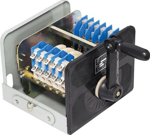
Overview of LK16 series master controller structure:
1. In order to meet production needs, this series of controllers have two types of control mechanisms (1): handle type and handwheel type. Generally used for handle type installation, it is horizontally installed, and its handle can work perpendicular to the handle or on the same axis as the handle. Hand wheel type is suitable for vertical installation. The base frame is connected to the upper and lower pillars through pillars (4) and screws, so that the contact group (7) can be fixed to the left and right pillars (4). The cam shaft (8) is formed by stacking cam plates, and the positioning ratchet (11) is installed at the tail of the shaft. Its axial fastening is achieved by fixing the bolt at the handle end with the washer (13) at the tail end, the bow plate (12), and the bolt. The positioning mechanism is composed of the same suspension (6), spring support (9), and two springs (14). Roller 10 is installed on the spring support (9) through a plastic sleeve to roll relative to the ratchet wheel. The base frame can be installed on the base (5) and covered with a cover (3) to form a protective type
2. The structure of the controller is detailed in Figure 1
1. Control mechanism 2, end cover 3, cover 4, pillar 5, bottom seat 6, suspension 7, contact group
8. Cam shaft 9, spring support 10, roller 11, ratchet 12, bow plate 13, washer 14, spring
Installation, use and maintenance
2. The appearance and installation dimensions of the controller are shown in Figure 2, Figure 3, and Table 4.
(1) During installation, the controller must be securely mounted on a wall or bracket, with two directional leads on the base of the controller.
(2) The controller should be inspected regularly, at least once a week, and must comply with the following requirements.
I: A thin layer of lubricant (industrial Vaseline can be used) should be regularly maintained in the friction area.
II: The working surface of the contact should have no large spots, and the melted area can be repaired with fine filing force. It is not allowed to use sandpaper.
III: All threaded connections must be tightened, especially at the connection points of the contacts.
IV: It is necessary to regularly remove dust and dirt from the controller, which can be wiped with compressed air or a dry cloth. V: Damaged parts should be replaced in a timely manner
vulnerable parts
Figure 2
Figure 3 shows the external appearance of the LK16 series non adjustable master controller
Table 4
|
Number of control circuits |
size | ||
|
A |
B | ||
|
twelve |
one hundred and ninety |
seventy | |
|
six |
one hundred and thirty-six |
||
LK16 series master controller
Home|Quality Commitment|Ordering|Payment method|product delivery|support|Disclaimer|Contact Us
Copyright®2011 www.91way.com Copyright.
Phone:+86-21-66770508 +86-13916500500 Fax:+86-21-66108310
Email:91way@163.com Wechat:40606422
沪ICP备2021005791号 ![]() 沪公网安备31010702003255号
沪公网安备31010702003255号