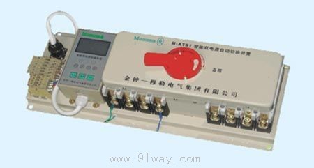
M-ATS1 series intelligent dual power automatic switch
Overview and Scope of Application
With the rapid development of technology today, power system equipment is gradually moving towards centralized monitoring and intelligence, that is, weak current (electronic) control of weak current Our company has developed a new generation of intelligent dual power automatic switching system based on advanced foreign technology and the actual needs of domestic electricity users It is based on the latest microcomputer control system, designed for electromagnetic compatibility, and resistant to
Strong interference, stable and reliable long-term operation, equipped with a large screen light LCD display, providing users with a good human-machine dialogue interface, easy operation and warning, and highly intelligent
An ideal mechatronics integrated new dual power automatic switching system This product uses 254 computer-controlled intelligent dual power supplies to operate simultaneously, greatly reducing manpower, material resources, and financial resources At the same time, it has ushered in a new era of intelligent and networked development for dual power automatic switching systems, and is also an updated product of similar products in China
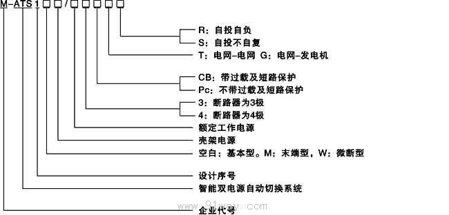
Model and meaning
Scope of application
The M-ATS1 system intelligent dual power automatic switching system is suitable for dual power supply with AC 50Hz/60Hz, rated voltage below 1000V, and rated current below 2000A
The electrical system can automatically switch between the common power supply (N) and the equipment power supply (R) (manual switching can also be set), enabling dual power supply users to achieve unmanned substations this
The product is suitable for special categories, power systems, high-rise buildings, residential areas, military facilities, hospitals, airports, docks, shopping malls, communication, fire protection, metallurgy, chemical industry, textiles, petroleum, coal mines and other important places that do not allow power outages
Normal working conditions
1. The ambient air temperature ranges from -25 ℃ to 40 ℃, and the average value over 24 hours does not exceed+35 ℃
2. Atmospheric conditions: The air is clean, and the relative temperature does not exceed 50% at the highest temperature of+40 ℃. Higher relative temperatures are allowed at lower temperatures, such as 90% at+20 ℃, but condensation may occur due to temperature changes
3. The installation location shall not exceed an altitude of 2000 meters and shall be used indoors
4. This product should be installed in a location where there is no severe vibration or impact, and where electrical components are not subjected to undue corrosion
If the above conditions cannot be met, the user manufacturer should negotiate and resolve the issue
When this product is used in offshore oil and nuclear power plants, a separate technical agreement should be signed
structural characteristics
The M-ATS1 intelligent dual power automatic switching system (hereinafter referred to as the intelligent system) consists of two main parts: the device body and the intelligent automatic controller
a. The device body consists of two circuit breakers with motor operating mechanisms (see technical parameter terms for model specifications) and accessories (auxiliary alarm contacts, etc.) with mechanical interlocking mechanisms and electrical interlocking
Fuses and wiring terminals are composed of isosceles triangles, and all components are installed on a single piece of metal
b. The intelligent automatic controller is composed of a novel microcontroller and various horizontal blocks such as outputs
2. The two are connected through a dedicated aviation plug interface and a shielded cable with a length not exceeding 2 meters Form an intelligent control system that controls the power supply voltage to 220V, 50/60Hz
3. This intelligent system has mechanical and electrical interlock protection functions, providing a safe and reliable guarantee for your power supply
4. This intelligent system can automatically switch between dual power supply of three-phase three wire and three-phase four wire
performance
Working principle of intelligent system
a. The controller simultaneously detects two voltages, and judges any voltage higher than 110% (adjustable) of the rated value as overvoltage, and any voltage lower than 85% (adjustable) of the rated value as undervoltage (or loss) voltage. The microcomputer control circuit makes logical judgments on the above detection results, and the processing results are sent to the electric operating mechanism through a delay (reliable) circuit to drive the corresponding instructions to open or close the circuit. The above detection results can be displayed on the LCD screen of the intelligent automatic controller panel, or connected to the computer through a serial port and controlled by software for the user to find the cause. The user can restore the fault line in a short time and restore the dual power supply to its original state
Intelligent automatic controllers are divided into three types according to their control functions
Self investment and self recovery (R) are applicable to power grids and power grids The intelligent automatic controller automatically switches between two power sources, namely the common power source and the backup power source. In normal state, the standby power source supplies power. When the common power source fails or is abnormal (overvoltage, undervoltage, undervoltage or undervoltage of any phase), it automatically switches to the backup power source for a set (adjustable) delay time. When the common power source returns to normal, the set (adjustable) delay time automatically returns to the common power source for power supply. When the backup power source fails or is abnormal (overvoltage, undervoltage, undervoltage or undervoltage of any phase), the controller triggers an alarm for the permanent or backup power source
Specifications and Technical Parameters
1. Self investment without self recovery (S) is applicable to power grids and power grids
The automatic controller that automatically switches between two power sources (i.e. common power source and backup power source) without self recovery Any abnormality occurs in any power supply (overvoltage occurs in any phase voltage)
When under voltage or phase loss occurs, it automatically switches to a normal power supply after a set delay, but cannot automatically recover when the abnormal power supply returns to normal
When used in the power grid and power generation system, the conversion time should be set at 15 seconds. The automatic controller of the power grid and power generation automatically controls the two power sources of the power grid and power generation
Switching, when the grid voltage is below 85% of the rated voltage, a power generation command is issued through a power generation delay command (output through a set of normally open and closed contacts) When the generated voltage reaches 85% of the rated voltage, the load circuit is first disconnected from the power grid, and the secondary load is unloaded (output through another set of normally open and closed contacts) through unloading instructions. Then, the generated power supply is connected with a delay through conversion After the power grid returns to normal (reaching 85% of the rated voltage or above), the intelligent controller will automatically disconnect the load circuit from the power source and switch to the power grid for power generation based on logical judgment
When the commonly used power supply is abnormal, the microcomputer will detect the current preset working status (manual, automatic, self resetting, non self resetting) and whether the backup power supply is normal to decide whether to switch and start the backup
Using power supply, the system load is powered by a backup power source
|
Current power supply for the load |
The current preset status of the system |
Is the current power supply faulty and is the other set of power supplies functioning properly |
Handling of power supply failures |
When the current backup power supply is normal, it will be detected and processed when there is power available again |
|
manual |
automatic |
Do not switch to |
switch to |
|
common |
backup |
common |
backup |
self-recovery |
Not self recovering |
common |
backup |
Is it commonly used normally |
Do not switch |
switch to |
|
● |
● |
|
|
● |
|
normal |
● |
|
|
|
|
|
|
abnormal |
● |
|
|
|
● |
|
|
|
|
|
normal |
|
|
● |
|
abnormal |
● |
|
|
|
● |
|
|
|
|
|
normal |
|
|
● |
|
abnormal |
● |
|
|
|
|
● |
|
● |
|
|
normal |
● |
|
|
|
● |
|
|
abnormal |
● |
|
|
|
|
● |
|
|
● |
|
normal |
|
● |
|
normal |
|
normal |
|
abnormal |
|
|
|
abnormal |
● |
|
|
|
● |
|
|
|
● |
normal |
|
● |
|
|
● |
|
|
abnormal |
● |
1. Dual power supply with dual split state
When the system load is in the dual split state, regardless of whether the two power supplies are normal or the preset states of "manual" and "automatic", the system still protects in the dual split state Only after operating the keyboard (manual) (automatic), will the system be switched to a non dual split state (manual - common - standby or automatic - self recovery - no self recovery), and the load will be powered and processed as described above
2. Protection function
Overload and short circuit protection; Phase failure, open circuit protection; Voltage loss and undervoltage protection
3. It has an automatic switching time that can be adjusted from 1 second to 30 seconds
4. High performance microcontroller program control, strong anti-interference ability, high protection accuracy
5. It has the advantages of small size, high stability, and reliable continuous operation
6. Equipped with a central microcomputer control communication port
7. Silent operation, energy-saving and consumption reducing, in compliance with national green electrical product standards
8. Equipped with remote control of fire signal output
Specifications and Technical Parameters
|
specification |
circuit breaker model |
Cabinet current A |
Rated working current A |
Breaking current KA |
Rated working voltage V |
Insulation voltage V |
frequency |
switch time |
Intelligent controller voltage V |
mechanical life |
|
M-ATS1-63/3 |
M-NZM series
M-NZS series
M-NZA series |
sixty-three |
3. 6, 10, 20, 25, 32, 40, 50, 63 |
Refer to the specific model circuit breaker manual |
four hundred |
one thousand |
50~60Hz |
Adjustable from 1 to 30 seconds |
AC220 |
Split and merge into one 5000 |
|
M-ATS1-63/4 |
|
M-ATS1-100/3 |
one hundred |
10. 16, 20, 32, 40, 50, 63, 80, 100 |
|
M-ATS1-100/4 |
|
M-ATS1-225/3 |
two hundred and twenty-five |
100, 125, 140, 160, 180, 200, 225 |
|
M-ATS1-225/4 |
|
M-ATS1-400/3 |
four hundred |
200, 250, 315, 350, 400 |
|
M-ATS1-400/4 |
|
M-ATS1-630/3 |
six hundred and thirty |
250, 315, 350, 40, 500, 630 |
|
M-ATS1-630/4 |
|
M-ATS1-800/3 |
eight hundred |
six hundred and thirty |
|
M-ATS1-800/4 |
|
M-ATS1-1250/3 |
two thousand |
eight hundred |
|
M-ATS1-2000/3 |
one thousand two hundred and fifty |
Installation diagram and wiring diagram
Intelligent controller dimensions, installation dimensions, and opening dimensions
Split type appearance and installation dimensions
Integrated appearance and installation dimensions
Principle of wiring diagram
Intelligent Controller Description and Settings
Intelligent Controller Panel Description
a. NA, NB, NC are commonly used power indicators; Illuminated indicates normal operation, idle indicates undervoltage or phase failure; RA and RB=RC are backup power sources.
b. Press the auto button to select the auto reset or non auto reset function. Pressing the double key can disconnect the load from the common or backup power source.
c. When the system malfunctions, the OA flashes, the alarm flashes, and an alarm sound is detected. Pressing the button can terminate the alarm. If the fault still persists, the alarm will sound again 30 seconds later.
M-ATS1 series intelligent dual power automatic switch