
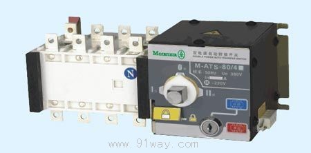
| Product name: | M-ATS2 Intelligent dual power automatic switching device | ||||||
| specification: |  |
||||||
| Category: | low-voltage electrical apparatus -- dual power switch | ||||||
| Price: | factory price | ||||||
| Brand: | |||||||
| Place of Origin: | China | ||||||
| Available Quantity: | batch | ||||||
| delivery cycle: | Spot goods (or inquire by telephone) | ||||||
|
|||||||
|
Agreed Civil Heating Power Supply Ith |
20A |
40A |
63A |
80A |
|
Rated insulation voltage Uone |
750V |
|||
|
Rated impulse withstand voltage Uimp |
8KV |
|||
|
Rated working voltage Ue |
AC440V |
|||
|
Rated working current Ie |
20A |
40A |
63A |
80A |
|
load characteristic |
AC31A、AC35A、AC33A |
|||
|
Rated connection capacity |
10Ie |
|||
|
Rated breaking capacity |
8Ie |
|||
|
Rated limit short-circuit current |
100KA |
|||
|
Rated short-time withstand current IS |
7KA |
|||
|
Convert time |
0.45S |
|||
|
Control power supply voltage |
AC220V |
|||
|
Motor energy consumption |
Start 300W, normal 55W |
|||
|
Weight (Kg) |
four point two |
four point three |
four point four |
four point five |
Terminal wiring diagram (without double division)
Note: HL1 and HL2 are indicators for incoming calls from the common power supply and backup power supply, respectively; HD1 and HD2 respectively indicate the activation of the common power supply and backup power supply; FU1 and FU2 are 2A fuses; 302~305 are switch terminals.
Terminal wiring diagram (with double split)
M-ATS2-100-1600A external installation dimensions
M-ATS2-2000A-3200A external installation dimensions
M-ATS2-100A-3200A Terminal Wiring Diagram
Fire control signal
The switch has a normally open contact for external connection to provide users with fire control signals. When a fire occurs, the fire control center sends a control signal to enter intelligent control. At this time, the dual power supply body enters the open state and cuts off the power supply at the load end. When the fire signal is not released, regardless of whether it is in the "manual" or "automatic" state, the common and backup power supply execution switches of the automatic transfer switch cannot be closed. Only after the fire control signal is released, the switch automatically switches to normal power supply from the common power source.
function
Control function:
The "normally" switch in the three status positions is closed, and the "standby" switch is open; The 'backup' switch is closed; The 'normally' switch is disconnected; Both switches are disconnected to the 0 position.
Multiple operation modes: emergency manual operation, manual control operation, automatic control operation.
The switch is controlled by a single-chip control device to achieve automatic operation function, and the reliable working voltage of the control motor of the main circuit is: the upper limit is 220 × 115% V, the lower limit is 220 × 75% V, and the frequency is 50HZ+10%.
Detection and protection function:
The working voltage of the various wiring terminals of the power supply is considered overvoltage when it reaches 115% of the rated working voltage; When the working voltage of the various wiring terminals of the power supply drops to 75% of the rated working voltage, it is considered undervoltage; If the working voltage of any phase terminal of the power supply drops to 75% or below of the rated working voltage, it is considered as voltage loss, which is abnormal. The common power supply and backup power supply are both part of the mains power supply system, and one power supply can be determined as the common power supply. When any phase of the common power supply circuit loses voltage, the switch will automatically switch to the backup power supply circuit after a delay of 3 seconds. When the common voltage circuit returns to normal, the switch will automatically switch to the common power supply circuit after a delay of seconds; The commonly used power supply circuit is the mains power supply, and the backup power supply circuit is the power supply system of the oil engine. When any phase of the commonly used power supply circuit loses voltage or all phases simultaneously experience overvoltage or undervoltage, the momentary switch will automatically switch to the disconnect position after a delay. At the same time, the control device will send a signal to start the oil engine. After the start is complete (i.e. no fault), the momentary switch will automatically switch to the backup circuit of the oil engine after a warm-up delay. When the backup power circuit of the oil engine is supplying power and the common power circuit returns to normal, after a delay of 3 seconds, the switch automatically switches to the common power circuit.
When the backup power circuit of the oil engine is supplying power, if any phase loses voltage or all phases simultaneously experience overvoltage or undervoltage, and if the common power circuit returns to normal, the switch will automatically switch to the disconnected position after a delay of 3 seconds.
When the switch is in the off position, as long as the common power circuit returns to normal and after a delay of 3 seconds, regardless of the state of the oil machine, the switch will automatically switch to the common power circuit first. When both the common power supply and the backup power supply fail, the switch should automatically switch to the disconnected position.
When the common power supply and the backup power supply lose voltage or undervoltage to 220 × 75% or below simultaneously, the switch fails and remains in its original position.
Computer communication function:
After connecting to the computer, this machine can directly monitor and control the conversion switch (please specify this function when ordering).
Function annotation:
Self investment and self recovery (R) are applicable to power grids. After the commonly used power supply returns to normal, it will automatically return to the commonly used power supply after a set (adjusted) delay time.
Self investment without self recovery (S) is applicable to power grids. The automatic controller that automatically switches between two pairs of intermediate power sources (i.e., the common power source and the backup power source) without self restoration. When any power supply experiences an abnormality (overvoltage, undervoltage, or phase loss in any phase voltage), it will automatically switch to another power supply after a set delay. However, when the abnormal power supply returns to normal, it cannot automatically recover.
When used in the power grid and power generation system, the self controller automatically switches between the power grid and the two power sources. When the grid voltage is below 85% of the rated voltage, a power generation command is issued through a power generation delay command (output as a set of normally closed contacts). When the generated voltage reaches 85% of the rated voltage, the load circuit is disconnected from the power grid first, and then the generated power supply is connected after a delay. After the power grid returns to normal (reaching 85% of the rated voltage or above), the intelligent controller will automatically disconnect the load circuit from the power source and switch to power supply from the grid
Fire release device:
DC24V is added, immediately cut off the two currents.
Home|Quality Commitment|Ordering|Payment method|product delivery|support|Disclaimer|Contact Us
Copyright®2011 www.91way.com Copyright.
Phone:+86-21-66770508 +86-13916500500 Fax:+86-21-66108310
Email:91way@163.com Wechat:40606422
沪ICP备2021005791号 ![]() 沪公网安备31010702003255号
沪公网安备31010702003255号