purpose
Used as a warning signal or accident signal circuit control component for repeated actions in electrical signal circuits of power generation and supply systems.
characteristic
ˇđ High sensitivity: minimum impulse action current of 0.01A.
ˇđ Anti interference: Only when the pulse width is greater than 160mS will it operate. Strong electrical and magnetic interference, pulling and closing the relay power supply, and voltage fluctuations of the relay power supply will not cause misoperation.
ˇđ High current: Maximum long-term steady-state current of 3.2A, absolutely no sampling resistor burnout problem.
ˇđ Multifunctional: Equipped with automatic reset delay element, delay warning signal delay element, suitable for instantaneous and delayed warning signals and accident signals of various types of light signs such as semiconductor light-emitting diodes and incandescent lamps. No intermediate or time peripheral relays are required, and the alarm bell or horn can be directly driven. Some varieties can restore both positive and negative electricity, making it convenient for on-site updates.
High tech: patented technology, computer-aided design, adoption of imported special sensor components, ensuring the aforementioned high performance.
ˇđ High reliability: Key components adopt imported branded electronic components, which work stably.
ˇđ Multiple varieties: There are various chassis products from Aji, Xuji, and Shangji, which can replace all existing impact relay products.
Working principle diagram and explanation
The power isolation sampling element connected in series in the DC signal circuit converts the continuous (rectangular) current pulse added in the circuit into a voltage signal and isolates it from the DC signal circuit. This voltage signal is detected by the action pulse width discrimination element after passing through the sudden change pulse detection element, and then sent to the signal self holding and release element for self holding. After being delayed by the action delay element, it reaches the output element and turns on the warning signal alarm bell. If the current in the signal circuit decreases by one circuit before the action delay element is delayed, the sudden change pulse detection element detects the reduced sudden change pulse, and after returning to the reset pulse width discrimination element, the signal self holding and release element returns. The action delay element returns, and the entire impulse relay returns. This is applied to the case of delay warning signal. The sentence is:. If applied to instantaneous warning signals or accident signals, switches S1 and S2 are opened. At this time, the reset pulse width discrimination element and the action delay element are both released. After adding one circuit to the signal circuit, the impulse relay immediately acts, and even if the pulse disappears, it does not return. After the impulse relay acts, the signal self holds and the release element returns through the delay of the reset delay element, and the impulse relay returns. If automatic reset is not required, S3 can be turned on, and the reset delay element is disabled. Simply add power to the reset terminal to return the impulse relay.
Using special sensors and electronic technology, it can withstand strong electrical and magnetic interference from power plants and substations, without misoperation. The impulse action current can be sensitive up to 0.01A, and the steady-state current can be as high as 3.2A. There is absolutely no problem of other impulse relay sampling resistors burning out. It has technical indicators and performance that cannot be compared to existing technology shock relays.
Model Comparison Table
|
model |
Exterior structure |
Return method |
Equivalent substitution |
Old product factory |
|
CC-10 |
CL10 |
1. Reset terminal+electrical reset
2.+Power loss reset
3. Internal automatic delay 4S reset (by S)threeControl works, special delayed ordering instructions). |
CJ-1 |
Aji |
|
CC-23 |
JK-2 |
ZC-21 |
Aji |
|
CC-2 |
A11K |
JC-2 |
Xu Ji |
|
CC-23A |
JK-2 |
1. Reset FG terminal+or - electrical reset
2. Power loss reset
3. Internal automatic delay 4S reset |
ZC-23 |
Aji |
|
CC-4YA |
shell-less |
BC-4Y inside a single shell |
Upcoming |
|
CC-4SA |
shell-less |
BC-4S inside a single shell |
Upcoming |
Main technical parameters
Rated voltage: DC 220V, 110V, 48V, allowable operating voltage: 80%~110% Ue, DC power supply voltage ripple factor not exceeding 2%.
ˇđ Impact action and return current: 0.01A; maximum stable current: 3.2A
There is a delay action element with a delay of 3.5S and a reset delay element with a delay of 8S inside, which are controlled by switches S2 and S3 respectively. If other values are required for the above delay, they can be specified at the time of ordering to meet user requirements. The accuracy of the delay element is ˇŔ 10%.
Output contact capacity: In the DC circuit of an inductive load with a current not exceeding 2A, voltage not exceeding 250V, and time constant of 5ms, the breaking capacity of the relay contact is 30W, and the relay contact is allowed to connect 5A current.
Power consumption: DC circuit: 3.2A<1.2W.
ˇđ Electrical lifespan: 100000 cycles.
|
Condition/Voltage |
220V |
110V |
48V |
|
before action |
ˇÜ5.5W |
ˇÜ3W |
ˇÜ1.5W |
|
After the action |
ˇÜ10W |
ˇÜ5W |
ˇÜ2W |
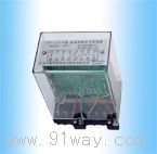
Structure, Terminal and Internal Wiring Diagram
|
|
|
CC-2 |
CC-10 |
CC-23 |
 |
|
CC-23A |
CC-4SA (back view) |
CC-4YA (back view) |
Internal wiring diagram of impact relay (front view)
Application reference diagram
| Small busbar and fuse |
matter
therefore
letter
number |
|
Test button |
|
power supply |
|
electric whistle |
|
Reset button |
|
Circuit breaker monitoring |
| Small busbar and fuse |
instant
time
pre-
announce
letter
number |
| Test button |
| power supply |
| contact point |
| Reset button |
| Reset button |
delay
time
pre-
announce
letter
number |
| power supply |
| alarm bell |
| return |
| Circuit breaker monitoring |
accident signal
Fuse blown |
Preview signal
Fuse monitoring light |
CC-2 application reference diagram (replacing JC-2)
| Small busbar and fuse |
matter
therefore
letter
number |
|
Test button |
|
power supply |
|
electric whistle |
|
Reset button |
|
Circuit breaker monitoring |
| Small busbar and fuse |
instant
time
pre-
announce
letter
number |
| Test button |
| power supply |
| contact point |
| Reset button |
| Reset button |
delay
time
pre-
announce
letter
number |
| power supply |
| alarm bell |
| return |
| Circuit breaker monitoring |
accident signal
Fuse blown |
Preview signal
Fuse monitoring light |
CC-23A application reference diagram (replacing ZC-23)