
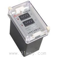
| Product nameŁş | SSJ-42B type static time relay | ||||||
| specificationŁş |  |
||||||
| CategoryŁş | low-voltage electrical apparatus -- time relay | ||||||
| PriceŁş | factory price | ||||||
| BrandŁş | |||||||
| Place of OriginŁş | China | ||||||
| Available QuantityŁş | batch | ||||||
| delivery cycleŁş | Spot goods (or inquire by telephone) | ||||||
|
|||||||
I. Overview
1. Main purpose of the product
The SSJ series static time relay (hereinafter referred to as the relay) is used in the secondary circuit relay protection and automatic control circuit of the power system as an extension
Set the controlled component to obtain the required delay. This relay is an integrated circuit static relay with high precision, low power consumption, accurate action time, and intuitive setting
Convenient and wide range, the working power supply adopts switch power conversion, AC/DC universal, and can completely replace electromagnetic time relays.
2ˇ˘ Classification and meaning of relay models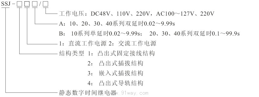
Comparison Table of SSJ-42B Static Time Relay Models and Replaced Old Models: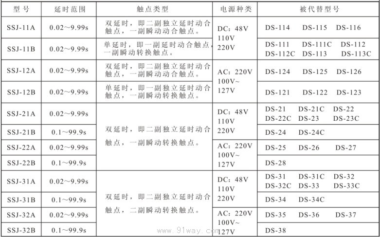
3ˇ˘ Product composition and working principle
1. The delay accuracy of SSJ-42B static time relay is much higher than that of DS electromagnetic time relay, which can meet the requirements of shortening the protection time difference in power system relay protection. It is currently an ideal replacement product for time relays. The external structure, internal wiring, working mode, and setting range of this relay are the same as those of the DS series time relay, except for the setting mode. The setting time is calculated by multiplying the three digits of the dip switch by the 0.01s or 0.1s time base. Changing the setting value does not require verification.
2. This relay is an action delay digital time relay composed of imported CMOS integrated circuits. The relay consists of an oscillator, a frequency divider, and a three-stage pulse counter, and the delay value is set through a BCD code dip switch.
3. Relays are usually not charged. After applying the rated voltage, the internal instantaneous relay of the relay acts and the crystal oscillator starts oscillating, generating clock pulses. After frequency division, the number of pulses is counted by the counter. When the counted number of pulses reaches the delay setting value, the trigger flips and drives the output relay to act, achieving the required delay. Due to the use of a crystal oscillator and the addition of a time compensation preset circuit, it strictly meets the setting value for extremely short delay values and has extremely high accuracy.
4. The double delay loop of the relay has relatively independent delay and drives one executing relay separately. Therefore, the dynamic closing contacts of the two executing relays can be used as the stopping and sliding contacts of the relay according to the length of the delay. However, after the sliding contact is closed, its closed state remains until the relay loses power and returns. If the user needs the sliding contact to close for a certain period of time and return immediately, they need to specify it when ordering and provide the duration of the sliding contact's closure.
5. The schematic diagram of the relay is shown in Figure 1.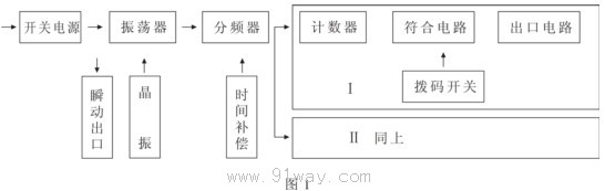
4ˇ˘ Technical requirements
1. The rated values and specifications are shown in the table above.
2. Delay accuracy
aˇ˘ The average error of the delay setting value: Under reference conditions, the absolute value of the average error of the relay delay setting value is not greater than 0.1%+3ms of the setting value; the average error=(average of 5 measurements - setting value)/setting value ˇÁ 100%.
bˇ˘ Delay consistency: Under benchmark conditions, the delay consistency of the relay is not greater than the set value (3-10ms).
cˇ˘ At temperatures ranging from -10 to 50 ˇć, the absolute value of the average error (including consistency) of any delay setting value shall not exceed 0.1%+5ms of the setting value.
3. Working voltage: When the operating voltage is not greater than 70% of the rated voltage, the relay should work reliably.
4. The return time of the relay to cut off the electrical power supply and the time for the outlet contact to return to the starting position should not exceed 25ms for varieties that use DC power supply.
5. When the return voltage of the relay decreases by no less than 10% of the rated voltage, the relay contacts should reliably return.
6. Power consumption
DC48VŁ¬ Not exceeding 2W;
DC110V or AC100-127V, not exceeding 4.5W (6.5VA)
DC or AC220V, not exceeding 8.1W (13VA).
7. Thermal performance requirements
This series of relays can operate for a long time when powered on, and can withstand 1.1 times the rated voltage value for a long time when the ambient temperature is 50 ˇć.
8. Power supply working characteristics: The power supply can slowly rise and fall, suddenly turn on/off, or supply power through shaking contacts. The relay can work normally and there is no zero second outlet or instantaneous outlet phenomenon.
5ˇ˘ Internal wiring of SSJ-42B static time relay (front view)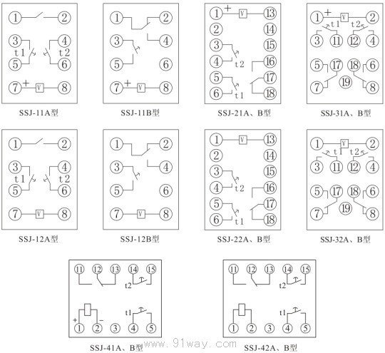
6ˇ˘ Appearance and opening size
SSJ-10 adopts a protruding fixed structure, and the appearance and installation hole size are detailed in Figure 1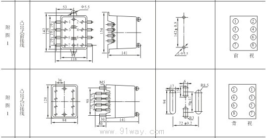
The SSJ-20 adopts a protruding plug-in structure, and the appearance and installation hole size are detailed in Figure 2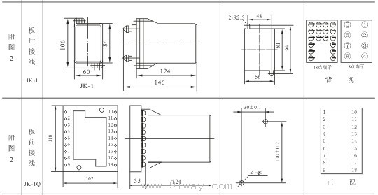
SSJ-30 adopts an embedded insertion structure, and the appearance and installation hole size are detailed in Figure 3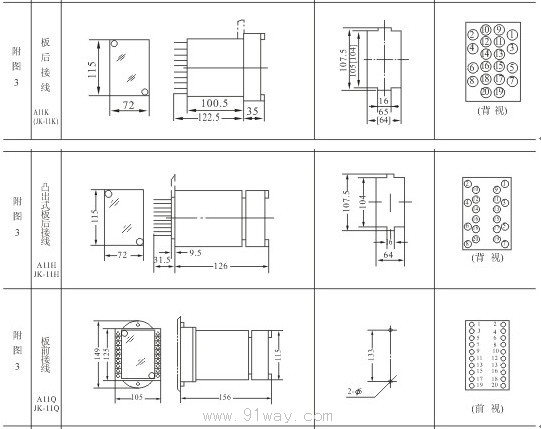
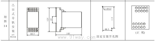
SSJ-40 adopts a protruding guide rail structure, and the appearance and installation hole size are detailed in Figure 14
HomeŁüQuality CommitmentŁüOrderingŁüPayment methodŁüproduct deliveryŁüsupportŁüDisclaimerŁüContact Us
Copyright®2011 www.91way.com Copyright.
PhoneŁş+86-21-66770508 +86-13916500500 FaxŁş+86-21-66108310
Email:91way@163.com Wechat:40606422
»¦ICP±¸2021005791şĹ ![]() »¦ą«Íř°˛±¸31010702003255şĹ
»¦ą«Íř°˛±¸31010702003255şĹ