
| Product nameЈє | YJGX-4FD Single phase circuit board DC solid-state relay | ||||||
| specificationЈє |  |
||||||
| CategoryЈє | low-voltage electrical apparatus -- solid state relay | ||||||
| PriceЈє | factory price | ||||||
| BrandЈє | |||||||
| Place of OriginЈє | China | ||||||
| Available QuantityЈє | batch | ||||||
| delivery cycleЈє | Spot goods (or inquire by telephone) | ||||||
|
|||||||
|
single |
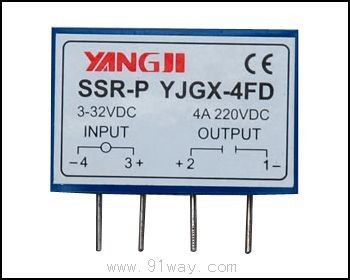
Product Model | YJGX-4FD | wiring diagram |
| Control method | Direct current controlled direct current (DC-DC) |  | |
| load current | 3AЎў4A | ||
| load voltage | 60VDCЎў110VDCЎў220VDC | ||
| control voltage | DC3-32V | ||
| control the current | 6-35mA | ||
| On state leakage current | ЎЬ1.5mA | ||
| On state voltage reduction | ЎЬ1.2V | ||
| Off state time | ЎЬ10mS | ||
| Dielectric Strength | 1500VAC | ||
| insulation resistance | 500M¦ё/500VDC | ||
| ambient temperature | -25Ўж-+70Ўж | ||
| Installation method | Printing layout PCB | ||
| weight | 16g | Note: When used for inductive loads, users must add suppression circuits |
Product application:
The SSR circuit board solid-state relay adopts a flame-retardant engineering plastic shell, epoxy resin encapsulation, single column direct insertion circuit board welding installation, and standard modular size. Compared with electromagnetic relays, it has no mechanical sound, no contact arcing, higher surge current tolerance, long service life, and high reliability.
The small driving current at the input end makes it convenient to interface with computer terminals and various digital programmable circuits, achieving weak power isolation and control.
Widely used in automation control fields such as petrochemical equipment, food machinery, packaging machinery, textile machinery, CNC machine tools, plastic machinery, fitness equipment, entertainment facilities, etc., it can control small motors, incandescent lamps, indicator lights, low-power power supplies, intelligent instruments and meters, and various solenoid valves. It can also be used as a driving stage for high-power electromagnetic contactors. Especially suitable for harsh environments such as corrosion, humidity, dust prevention, explosion-proof requirements, and frequent switching.
Safety precautions:
1. When used in AC inductive loads, high transient voltage and surge current are applied to the output terminal, which may cause the solid-state relay to conduct or be damaged. It is usually necessary to connect a voltage control device with a specific clamping voltage at the output terminal, such as a two-wire voltage regulator diode or a varistor (MOV). The recommended voltage for varistors is 1.6-1.9 times the rated voltage;
2. For DC inductive loads such as solenoids, electromagnets, and solenoid valves, a freewheeling circuit must be used to suppress the back electromotive force generated during shutdown. A simple method is usually to connect a diode in reverse parallel with the load, but this circuit will affect the release time of inductive loads such as electromagnetic relays, contacts, electromagnets, solenoid valves, etc. A better circuit is to connect a diode and a voltage regulator diode in reverse series or a diode and a resistor in series before connecting it in reverse parallel with the load.
3. When controlling a small current load close to the minimum load current, a virtual load resistor must be connected in parallel to the load to reduce the output leakage current and generate a higher residual voltage on the load.
4. When installing circuit board welding type relays, the welding temperature must be controlled below 260 degrees Celsius and the welding time must be controlled below 5 seconds.
5. In order to avoid the temperature rise of solid-state relays exceeding the allowable value, the design and application should consider the heat dissipation effect and installation position. When two or more solid-state relays are installed side by side, appropriate spacing should be left.
HomeЈьQuality CommitmentЈьOrderingЈьPayment methodЈьproduct deliveryЈьsupportЈьDisclaimerЈьContact Us
Copyright®2011 www.91way.com Copyright.
PhoneЈє+86-21-66770508 +86-13916500500 FaxЈє+86-21-66108310
Email:91way@163.com Wechat:40606422
»¦ICP±ё2021005791єЕ ![]() »¦№«Нш°І±ё31010702003255єЕ
»¦№«Нш°І±ё31010702003255єЕ