
 Your location:Home → mechanical transmission → Brake | Clutch → electromagnetic brake → AZM series three-phase power-off brake
 |
Product name: | AZM series three-phase power-off brake | |||||
| specification: |   Zoom in on the image Zoom in on the image |
||||||
| Category: | mechanical transmission -- electromagnetic brake | ||||||
| |
Price: | factory price | |||||
| Brand: | Shanghai | ||||||
| Place of Origin: | China | ||||||
| |
Available Quantity: | batch | |||||
| delivery cycle: | Spot goods (or inquire by telephone) | ||||||
 |
|
||||||
|
Specification code |
AZM71 |
AZM80 |
AZM90 |
AZM100 |
|
Matching YEJ motor frame number H |
seventy-one |
eighty |
ninety |
one hundred |
|
Static braking torque Nm |
fourteen |
eighteen |
thirty-eight |
fifty |
|
Braking time ≤ S |
zero point one zero |
zero point one zero |
zero point one five |
zero point one five |
|
Excitation power ≤ w |
twenty |
twenty-five |
thirty |
thirty-five |
|
Normal working air gap mm |
0.20~0.25 |
0.25~0.30 | ||
|
Maximum wear air gap mm |
zero point five zero | |||
|
Rated working voltage V |
3Φ-220/380 | |||
|
Connection method |
△/Y | |||
|
insulation class |
F | |||
|
Allow maximum speed r/min |
three thousand and six hundred | |||
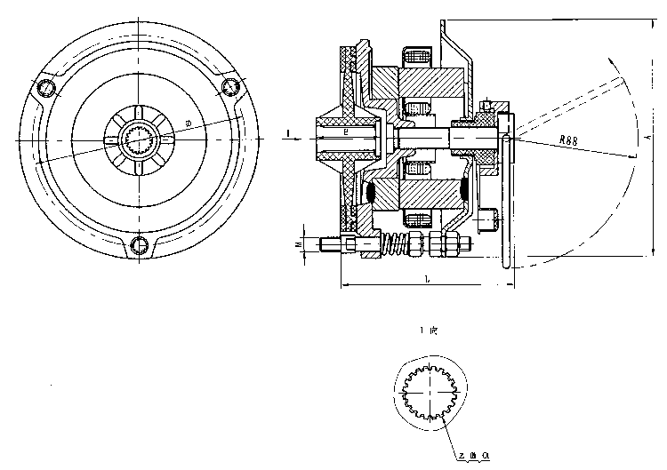
|
Specification Code |
Installation dimensions and tolerances |
External Dimensions |
|||||||
|
Z (number of teeth) |
M (modulus) |
α (pressure angle) |
E |
Φ |
n-s×h |
A |
L |
||
|
Involute spline teeth |
basic size |
basic size |
basic size |
||||||
|
AZM71 |
twenty |
zero point eight |
30° |
thirty-six point five |
one hundred and twenty |
3×M8×12 |
Φ137 |
ninety-seven |
|
|
AZM80 |
twenty-four |
zero point eight |
30° |
forty-one point five |
one hundred and forty |
3×M8×12 |
Φ154 |
one hundred |
|
|
AZM90 |
thirty |
zero point eight |
30° |
fifty-five |
one hundred and fifty-eight |
3×M8×12 |
Φ174 |
one hundred and ten |
|
|
AZM100 |
thirty-eight |
zero point eight |
30° |
fifty-five |
one hundred and seventy-seven |
3×M8×12 |
Φ194 |
one hundred and thirteen | |
Note: Unit (mm)
Structure, Installation and Debugging Diagram: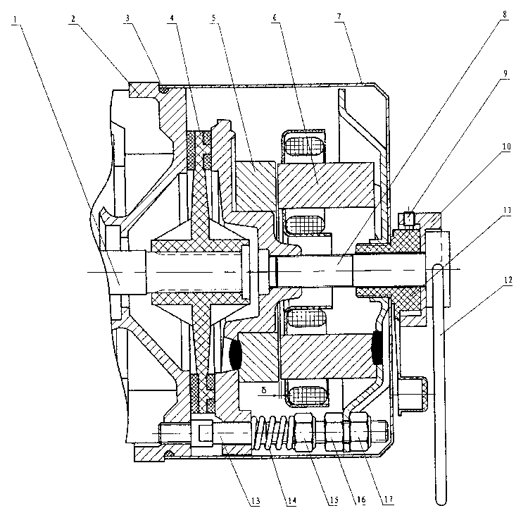
1. Rotor 2, brake mounting seat 3, O-ring seal 4, brake disc assembly 5, armature assembly 6, magnetic yoke assembly 7, brake cover 8, release screw 9, fixing screw 10, manual release seat 11, cover fixing screw 12, release wire ring 13, double headed fixing bolt 14, formulated spring 15, brake torque adjustment nut 16 (17), air gap adjustment nut δ, working air gap
Air gap debugging method:
Tools: stiff hand, feeler gauge.
Debugging method: Unscrew the (11) nut and screw, remove the protective cover (7), loosen the (16) and (17) 6 nuts, select the working air gap thickness plate according to the model of the plug gauge, insert it near the δ point of one of the fixed screws (13), screw in (17) to press the plug gauge, and then slightly withdraw it. The plug gauge can be removed, but it should not be too loose. Then it is necessary to tighten the tight nut (16) and use the same method to adjust the other 2 points that are 120 ° apart. Finally, check if the air gap is the same. If it is too tight or too loose, adjust it to achieve uniformity at three points. After long-term wear and tear of the friction plate, the δ value must be checked. When the "δ" value exceeds the maximum wear air gap value, the above method must be used for adjustment, otherwise it will affect the normal operation of the brake.
Notes:
1. The surface of the armature, rear end cover, and brake disc must be free of oil stains and kept dry and clean;
2. During installation and debugging, it is necessary to ensure that the air gap "δ" value is within the working air gap range;
3. The involute spline shaft is processed according to the 7th level standard, mainly based on the matching of brake disc teeth. When assembling the brake disc, apply an appropriate amount of butter to the spline teeth.
 Related Products:
 200DZ01 type electromagnetic power-off brake .. J130DZ03 type electromagnetic power-off brake.. J128DZ01,J128DZ02 type electromagnetic power-.. 118DZ01,118DZ02 type electromagnetic power-of.. J100DZ01,J100DZ02 type electromagnetic power-.. J95DZ01 type electromagnetic power-off brake .. 80DZ01,90DZ01 type electromagnetic power-off .. 75DZ series electromagnetic power-off brake 7.. 70DZ01 type electromagnetic power-off brake 63DZ01 type electromagnetic power-off brake Related articles:
 speed reducer
  conveyor elevator gearbox divider backstop Brake | Clutch Brake rectifier electromagnetic brake
  Magnetic particle brake eddy current brake Hydraulic thruster Hydraulic brake system electromagnetic clutch Magnetic Particle Clutch Combination clutch Centrifugal clutch overrunning clutch Cam clutch one-way clutch hydraulic clutch Pneumatic brake pneumatic clutch hydraulic coupling buffer shock absorber drive belt drive wheel drive shaft coupling expansion sleeve Chain wheel chain motor bearing motorized roller industrial remote control
 Home|Quality Commitment|Ordering|Payment method|product delivery|support|Disclaimer|Contact Us
Copyright®2011 www.91way.com Copyright.
Phone:+86-21-66770508 +86-13916500500 Fax:+86-21-66108310
Email:91way@163.com Wechat:40606422
沪ICP备2021005791号  沪公网安备31010702003255号

