
 Your location:Home → Hardware tools → hydraulic tool → Hydraulic bending tool → Electric hydraulic bending machine
 |
Product name: | Electric hydraulic bending machine | |||||
| specification: |   Zoom in on the image Zoom in on the image |
||||||
| Category: | Hardware tools -- Hydraulic bending tool | ||||||
| |
Price: | factory price | |||||
| Brand: | Shanghai | ||||||
| Place of Origin: | China | ||||||
| |
Available Quantity: | batch | |||||
| delivery cycle: | Spot goods (or inquire by telephone) | ||||||
 |
|
||||||
| model | DWP-10A | DWP-12A |
| Bending angle a | л/2≤a<л | л/2≤a<л |
| Bending radius mm | 2.5 times the row width | 2.5 times the row width |
| Bending thickness mm | 4 5 6 8 10 | 4 5 6 8 10 12 |
| Bending width mm | 40 50 60 80 100 | 40 50 60 80 100 120 |
| Maximum pressure Mpa | forty-five | fifty |
| Maximum travel mm | two hundred and fifty | three hundred and twenty |
| Hydraulic oil grade | N15 | N15 |
| The parameters in the table may change due to improvements without prior notice. | ||
Hydraulic separation bending machine is a new type of bending machine for aluminum and copper bars
It has a reasonable structure, easy operation, and safe use. 1、 Structure
By manual pump (electric pump) (16), high pressure; Oil pipeline (13), quick connector (2), working cylinder
(1) Bending components (including upper and lower flower boards, clamp mold heads, right angle mold heads, roller columns, etc.)
Composed of R templates, etc. See attached sketch:
2、 Purpose:
The bending machine is mainly suitable for power supply bureaus, substations, and a large number of power companies to install electricity
Bending and repairing of aluminum or copper bars in power lines.
3、 Performance characteristics: (technical parameters)
1. Maximum working pressure: 63MPa
2. Maximum travel: 200mm
3. Bending range: Copper bar width 40, 50, 60, 80, 100, 120mm thickness: between 4-12mm
4. Bending angle: d>90 degrees, any angle
5. Bending radius: R=Row width × 2.5
6. Oil type: No.10 mechanical oil
7. Oil consumption: 600 milliliters
8. Total weight: 82 kilograms
4、 Usage and precautions of DWP electric hydraulic bending machine
1. Usage:
a、 First, insert the working oil cylinder (1) into the hole of the square block (3) and tighten the nut to the bottom. Tighten the nut and the square block tightly, then tighten the butterfly shaped fixing screw. Then, pull the outer sleeve of the quick connector at the end of the compression tube back and place it on the working cylinder joint to loosen it. Once the movable part returns to its original position, it can be fastened by itself. Finally, tighten the oil drain screw (15) on the pump body to start working. Similarly, when the work is completed, loosen the oil drain screw and the working cylinder will start working
It will automatically retract.
b、 When bending flat (as shown in Figure 1), open the upper flower plate (4) and install the clamp mold head (8) into the working oil cylinder head. According to the thickness of the bent row, R, Select R template (7) and aluminum row
Put the copper bars together into the clamp mold head, then press the clamp plate tightly. Align the groove width of the two roller columns (6) with the thickness of the aluminum and copper bars, and place them in the corresponding size holes. Then cover the upper flower plate and push the bent aluminum or copper bars into the groove, but the bars must extend more than 100mm from the roller columns. If the maximum row length exceeds 200mm, the top rod can be extended to fit the head of the working oil cylinder, and the other end can still be operated by installing it into the clamp mold head.
c、 When bending upright (see Figure 2), open the upper flower plate, install the right angle die head (9) into the head of the working oil cylinder, insert two 22 pins (11) into the hole (18) of the lower flower plate (5), and then cover the upper flower plate. Place the aluminum or copper bar between the pins and the right angle die head to work. The minimum distance between the two bent right angles is 40mm. If the bent R row needs to be bent upright again, open the upper flower plate, insert the connecting rod plate (10) into the T-shaped joint, insert the 12 long bolt, and insert the two 22 pins into the connecting rod plate to work.
d、 Under the standard bending radius R of row width x2.5 and bending angle d>90 degrees, the rebound angle can be achieved.
e、 The roller column has five grooves, which are used at two ends. The position of one end is 64mm below the position line of the flower board to the bottom of the groove. If the other end is used, it must be turned around.
f、 The oil pump needs to be refueled by removing the rubber cover (14) at the end of the pump and then unscrewing the M8 hex screw to expose the oil pipe for refueling.
g、 Copper bars need to be tempered before they can be used.
h、 R100、R125、R150、 Two 4mm plates are used for bending 8mm rows, and 5mm R plates are used for bending 6mm.
J、 Please refer to the user manual for the electric pump.
2. Precautions
a、 If there is a hollow phenomenon during use, you can first loosen the oil drain screw on the pump body
Lift the pump vertically and hit the head downwards a few times, then tighten the oil drain screw to continue
use.
b、 Never remove the quick connector when there is a load.
c、 This machine uses oil as the medium, and it is necessary to clean and maintain the oil and this machine properly
To avoid clogging or oil leakage, which may affect the effectiveness of use.
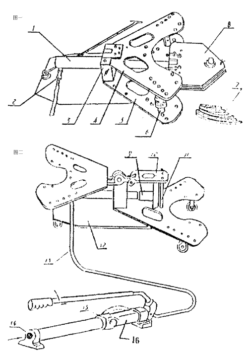
1. Working oil cylinder 2, quick connector 3, square block 4, upper flower plate 5, lower flower plate 6, roller column 7, R template 8, clamping plate mold head 9, right angle mold head 10, connecting rod plate
11. Pin 12, trolley 13, oil delivery pipe 14, rubber hose 15, oil drain screw 16, pump body
 Related Products:
 DWQJ-G76 Type Multi functional Rolling Pipe B.. SWG-4D Manual hydraulic pipe bending machine .. SWG-3B Manual hydraulic pipe bending machine .. SWG-2A Manual hydraulic pipe bending machine .. SWG-38 Multi functional manual pipe bending m.. STYW-60C Automatic hydraulic pipe bending mac.. STYW-60D Automatic hydraulic pipe bending mac.. DWQJ-76 Multi functional Rolling Pipe Bending.. SDW series manual and electric dual-use pipe .. SWG-25 Manual pipe bending machine Related articles:
 Universal Accessories Rubber hardware Cutting tools Measuring scales Welding equipment power tool pneumatic tool hydraulic tool
  hydraulic cylinder refueling truck hydraulic press oil purifier Hydraulic components hydraulic wrench hydraulic puller bearing heater Hydraulic hole punch Hydraulic crimping pliers hydraulic jack Hydraulic stretching tool Hydraulic bending tool
  Hydraulic cutting tool Bender|Threading machine manual tools Lifting tools power tools diamond tools abrasives and abrasive tools Mold casting Cleaning and lubrication Architectural Hardware Machinery and equipment
 Home|Quality Commitment|Ordering|Payment method|product delivery|support|Disclaimer|Contact Us
Copyright®2011 www.91way.com Copyright.
Phone:+86-21-66770508 +86-13916500500 Fax:+86-21-66108310
Email:91way@163.com Wechat:40606422
沪ICP备2021005791号  沪公网安备31010702003255号

