
 |
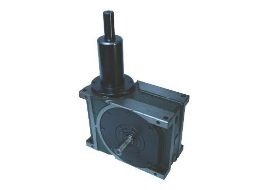
Product name: | DFN,DNFL series swing motion splitter | |||||
| specification: | 4.5DFN 70DFN 80DNF 80DNFL |   Zoom in on the image Zoom in on the image |
|||||
| Category: | mechanical transmission -- divider | ||||||
| |
Price: | factory price | |||||
| Brand: | Shanghai | ||||||
| Place of Origin: | China | ||||||
| |
Available Quantity: | batch | |||||
| delivery cycle: | Spot goods (or inquire by telephone) | ||||||
 |
|
||||||
|
Characteristic project |
symbol |
Unit |
numerical value |
Characteristic project |
symbol |
Unit |
numerical value |
Characteristic project |
symbol |
Unit |
numerical value |
|
Allowable radial load on the output shaft |
C1 |
kgf |
five |
Allowable radial load on the input axis |
C3 |
kgf |
sixty |
GD2 of the input axis (Note 1) |
C6 |
kgf-m2 |
3.9×10⁻⁴ |
|
Allowable axial load on the output shaft |
C2 |
kgf |
nine |
Maximum bending moment of the input axis |
C4 |
kgf |
forty-five |
Positioning and segmentation accuracy |
sec |
±30 | |
|
Allowable torque of output shaft |
Ts |
kgf-m |
Reference torque table |
Maximum torque of the input shaft |
C5 |
kgf-m |
thirty-eight |
Weight |
kg |
About 14.7 | |
|
Note 1: The GD2 of the input axis is a value within the stopping range. Note: The values from C1 to C5 are the values when the safety factor reaches 2. | |||||||||||
|
Characteristic project |
symbol |
Unit |
numerical value |
Characteristic project |
symbol |
Unit |
numerical value |
Characteristic project |
symbol |
Unit |
numerical value |
|
Allowable radial load on the output shaft |
C1 |
kgf |
seven |
Allowable radial load on the input axis |
C3 |
kgf |
one hundred |
GD2 of the input axis (Note 1) |
C6 |
kgf-m2 |
1.2×10⁻² |
|
Allowable axial load on the output shaft |
C2 |
kgf |
fourteen |
Maximum bending moment of the input axis |
C4 |
kgf |
ninety-five |
Positioning and segmentation accuracy |
sec |
±30 | |
|
Allowable torque of output shaft |
Ts |
kgf-m |
Reference torque table |
Maximum torque of the input shaft |
C5 |
kgf-m |
six |
Weight |
kg |
About 22 | |
|
Note 1: The GD2 of the input axis is a value within the stopping range. Note: The values from C1 to C5 are the values when the safety factor reaches 2. | |||||||||||
|
Characteristic project |
symbol |
Unit |
numerical value |
Characteristic project |
symbol |
Unit |
numerical value |
Characteristic project |
symbol |
Unit |
numerical value |
|
Allowable radial load on the output shaft |
C1 |
kgf |
fifteen |
Allowable radial load on the input axis |
C3 |
kgf |
one hundred and forty |
GD2 of the input axis (Note 1) |
C6 |
kgf-m2 |
1.7×10⁻² |
|
Allowable axial load on the output shaft |
C2 |
kgf |
eighteen |
Maximum bending moment of the input axis |
C4 |
kgf |
one hundred and ninety |
Positioning and segmentation accuracy |
sec |
±30 | |
|
Allowable torque of output shaft |
Ts |
kgf-m |
Reference torque table |
Maximum torque of the input shaft |
C5 |
kgf-m |
nine point five |
Weight |
kg |
About 33 | |
|
Note 1: The GD2 of the input axis is a value within the stopping range. Note: The values from C1 to C5 are the values when the safety factor reaches 2. | |||||||||||
|
Characteristic project |
symbol |
Unit |
numerical value |
Characteristic project |
symbol |
Unit |
numerical value |
Characteristic project |
symbol |
Unit |
numerical value |
|
Allowable radial load on the output shaft |
C1 |
kgf |
nine |
Allowable radial load on the input axis |
C3 |
kgf |
one hundred and forty |
GD2 of the input axis (Note 1) |
C6 |
kgf-m2 |
1.2×10⁻² |
|
Allowable axial load on the output shaft |
C2 |
kgf |
seventeen |
Maximum bending moment of the input axis |
C4 |
kgf |
one hundred and ninety |
Positioning and segmentation accuracy |
sec |
±30 | |
|
Allowable torque of output shaft |
Ts |
kgf-m |
Reference torque table |
Maximum torque of the input shaft |
C5 |
kgf-m |
nine point five |
Weight |
kg |
About 30 | |
|
Note 1: The GD2 of the input axis is a value within the stopping range. Note: The values from C1 to C5 are the values when the safety factor reaches 2. | |||||||||||
 Related Products:
 MWF300 series impact weak damping capacitive .. OW Type Return Oil Pipeline Water Divider CVDN series nitrogen based environmentally fr.. FJ56 Resistance voltage divider box DJ12 DC voltage divider box FJ12 DC voltage divider box RI80F High Voltage and High Resistance Glass .. TAWF AC voltage divider capacitor FYMJ type capacitive voltage divider NR series pulse voltage divider Related articles:
Home|Quality Commitment|Ordering|Payment method|product delivery|support|Disclaimer|Contact Us
Copyright®2011 www.91way.com Copyright.
Phone:+86-21-66770508 +86-13916500500 Fax:+86-21-66108310
Email:91way@163.com Wechat:40606422
沪ICP备2021005791号  沪公网安备31010702003255号
 Your location:




