Purpose:
JG-15 type power directional relay includes: JG-15A type zero sequence power directional relay; JG-15B phase to phase power directional relay. JG-15A type is used as a zero sequence directional element for transformer grounding protection in high current grounding systems. Reflect the direction of zero sequence current during ground short circuit. JG-15B type is used as a directional component for phase to phase short circuits, reflecting the direction of short-circuit current during phase to phase short circuits and wired at 90 ˇă.
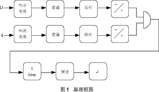
Working Principle:
The JG-15 power direction relay is constructed using the phase comparison principle. The phase comparison element measures the polarity overlap time t of two electrical quantities, that is, the phase angle difference ¦Ä, ¦Ä=180 ˇă -18 ˇă t, t is ms. The operating condition is t ˇÝ 5ms, that is, ¦Ä ˇÜ 90 ˇă.
Main technical parameters:
4.1 Rated AC voltage 100V; Rated AC voltage 1A, 5A; Frequency 50Hz.
4.2 Maximum sensitivity angle: Test JG-15A: -105 ˇăˇŔ 3 ˇă at rated AC voltage and current; JG-15B: -45 ˇăˇŔ 3 ˇă.
4.3 The range of motion shall not be less than 170 ˇă.
4.4 Minimum operating voltage ˇÜ 400mV.
4.5 Minimum operating current ˇÜ 5% rated AC current.
4.6 Action time ˇÜ 30ms.
4.7 Return time ˇÜ 50ms.
4.8 Overload Capacity
AC voltage circuit: capable of continuous operation at 1.2 times the rated voltage. AC current circuit: capable of continuous operation at twice the rated current;
10 times the rated current can operate continuously for 10 seconds
40 times the rated current can operate continuously for 1 second.
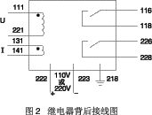
4.9 Auxiliary DC power supply: 110V or 220V.
4.10 Power consumption
AC voltage circuit: ˇÜ 1VA at rated voltage of 100V.
AC current circuit: ˇÜ 1VA at rated current of 5A
ˇÜ 0.5VA at rated current of 1A.
DC voltage circuit: 110V<3W, 220V<3W.
4.11 Environmental temperature: -10 ˇć -50 ˇć.
4.12 Dielectric Strength Relay: Each conductive circuit of the relay should be able to withstand an AC test voltage of 2kV (effective value) and 50Hz between exposed non charged metal parts and casings, as well as between input circuits and contacts, for a duration of 1 minute without insulation breakdown or flashover.
4.13 Working conditions
a) The usage location does not allow explosive media, and the surrounding media should not contain corrosive metals, gases that damage insulation, or conductive media. It is not allowed to be filled with water vapor or have serious mold presence;
b) Strong vibrations and impacts are not allowed in the usage location;
c) The usage location should have facilities to defend against rain, snow, wind, and sand;
d) The usage location does not allow an external magnetic induction intensity exceeding 1.5mT.
4.14 Electrical anti-interference relays shall comply with GB7261 and GB6261 "Electrical anti-interference tests for static relays and protective devices".
Wiring diagram behind the relay:
JG-15 power direction relay external dimensions and opening dimensions:
Refer to Figures 2 and 6 in the protruding modular insertion structure.
Ordering instructions:
6.1 Product model, name, structural form, etc.
6.2 Order Quantity.
6.3 Relay matching: such as base, socket, etc. (must be ordered separately).

