Purpose:
The BT-1B/R synchronous check relay is used in the automatic reclosing circuit of the two terminal power supply system as a checking element for voltage and synchronization.
Working Principle:
Principle of operation
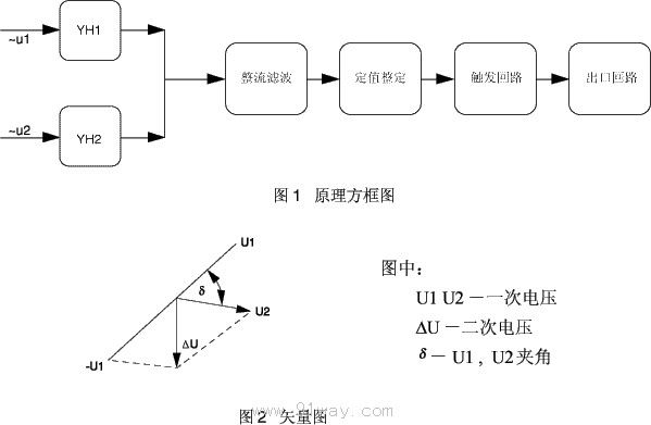
The relay consists of voltage transformers YH1 and YH2, rectification and filtering circuits, triggers, and reed relays. The schematic block diagram is shown in Figure 1
Two alternating voltages (or currents) are applied to the two primary windings of voltage transformers YH1 and YH2, respectively, with their secondary windings connected to the rectifier bridge in opposite polarity. When two voltages (or currents) are in phase at once, due to the reverse polarity connection of the secondary winding, the potential generated on the voltage transformer cancels each other out, and the secondary output voltage is equal to zero (the unbalanced voltage does not exceed 0.5V). The trigger is still in its original state (BG1 conducts, BG2 is cut off), and the reed relay does not operate. When the two voltages (or currents) are in different phases, the potential generated on the voltage transformer cannot cancel each other out, and the potential is generated on the secondary winding. The magnitude of the secondary output voltage is related to the phase difference and amplitude of the two voltages (or currents) on the primary winding. When the amplitude is constant, the larger the phase difference, the larger the secondary output voltage, and vice versa. The vector diagram is shown in Figure 2.
The secondary output voltage is rectified and filtered before being applied to the trigger. When the signal voltage reaches the set value, the trigger flips (BG1 is turned off, BG2 is turned on) and the reed relay acts, opening the dynamic breaking contact and closing the dynamic closing contact.
When any input voltage (or current) is zero or very low, the situation is the same as when two voltages (or currents) are in different phases, and the relay should also immediately act.
The setting of the relay action angle is achieved using potentiometer R8.
Main technical parameters:
3.1 According to the rated AC voltage, the specifications of the relay are shown in the table below
3.2 DC rated voltage: 220V, 110V, 48V.
3.3 Rated frequency: 50Hz.
3.4 Contact form: dynamic connection, dynamic disconnection.
3.5 Action angle setting range: 20 ˇă to 40 ˇă.
3.6 Return coefficient: not less than 0.85.
3.7 DC power supply variation: When operating at 220V and 110V, it is allowed to vary within the range of 80-110%; At 48V, it is allowed to vary within the range of 90-110%, and the relay should be able to work normally.
3.8 Power consumption: The relay AC circuit shall not exceed 1VA; the DC circuit shall not exceed 6W at 220V; the power consumption shall not exceed 4W at 110V, and the power consumption shall not exceed 2W at 48V.
3.9 Contact breaking capacity, for DC inductive load circuits with voltage not exceeding 220V and current not exceeding 0.2A (time constant not exceeding 5 ˇÁ 10-3s), the breaking capacity is 25W and 30VA in AC circuits.
3.10 Electrical lifespan: 5 ˇÁ 103 cycles.
3.11 Dielectric Strength Relay: Each conductive circuit of the relay should be able to withstand an AC test voltage of 2kV (effective value) and 50Hz between the exposed non charged metal parts and the casing, as well as between the input circuit and the contacts. After a 1-minute test, there should be no insulation breakdown or flashover phenomenon.
3.12 Working conditions
a) The usage location does not allow explosive media, and the surrounding media should not contain corrosive metals, gases that damage insulation, or conductive media. It is not allowed to be filled with water vapor or have serious mold presence;
b) Strong vibrations and impacts are not allowed in the usage location;
c) The usage location should have facilities to defend against rain, snow, wind, and sand;
d) The usage location does not allow an external magnetic induction intensity exceeding 1.5mT.
3.13 Electrical anti-interference relays shall comply with GB7261 and GB6261 "Electrical anti-interference tests for static relays and protective devices".
BT-1B/R synchronous inspection relay back wiring diagram:
The terminal diagram of the protruding modular insertion structure (BT-1B/R type) behind the relay is shown in Figure 3. There is a potentiometer on the panel, and R2 is used for setting the delta angle.
Relay external dimensions and opening dimensions:
Refer to Figures 4 and 8 in the protruding modular insertion structure.
Ordering instructions:
5.1 Product model, name, rated voltage, structural form, etc.
5.2 Order Quantity.
5.3 Relay matching: such as base, socket, etc. (must be ordered separately).

