Purpose:
JL-10ˇ˘ 20. The 30 series integrated circuit current relay is a static, non directional, transient, AC current relay. Can be used as a starting element in power system transmission lines, motors, overload and short circuit protection. Relays are not sensitive to the DC component in short-circuit currents, so they can be used in lines that require small transient exceedance. This relay is composed of integrated circuits, and its execution circuit has the characteristics of high sensitivity, fast action speed, low power consumption, and easy setting. The DC power supply and outlet relay of the relay are monitored by signal indicator lights, and the outlet relay has 2 sets of large capacity contact outputs. Users can directly control the protected equipment according to specific situations. The relay action value is set by the dial switch on the panel, which is intuitive and convenient.
Relay model name:
Note: (JL-10 represents protruding type, JL-20 represents protruding plug-in type, JL-30 represents embedded plug-in type) In order to facilitate users to replace various models of current relays, please refer to the table below for comparison
Working Principle:
The input current is converted into an appropriate voltage by a current voltage converter, and after setting the operating value and active bandpass filtering, it undergoes full wave rectification. The pulsating voltage is compared and integrated, and the detector judges the integrated voltage. When the integrated level exceeds the detection level, the detector outputs a high level to drive the output relay to operate.
This relay adopts a new type of integral judgment circuit, which makes the action time and return time of the relay fast, transient overtaking is also achieved, and it has strong anti-interference performance.

Usage:
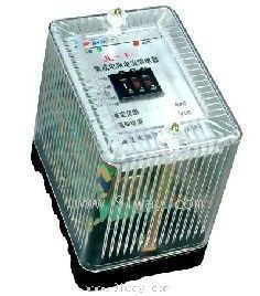
Firstly, please carefully observe the panel of this relay, where the four ID setting switches in the upper left corner are used for rough adjustment of the relay's current value. For example, if you have a relay with K=4 in your hand, when the 1K switch is turned on and the other switches are turned off, the ID setting value is 1 ˇÁ K=4A, and so on. You can obtain the setting values of 8A, 16A, and 32A through the other switches. If it cannot meet your needs, then use the MN dial switch in the lower left corner for fine adjustment. Please calculate according to the formula I=ID (1. MN) on the panel. The calculation method is as follows: If K=4, you need I=12A, you can first set the ID to 2K=8A. Then calculate M=5 and N=0 through the formula. After setting according to the above method, when the external current I=12A is applied, the right indicator light changes from green during normal operation to red, and the relay acts. The setting range is shown in the previous table.
Main technical parameters of JL series integrated circuit current relay:
5.1 Rated Value
a) Rated AC current: 0.1A, 1A, 5A;
b) Frequency: 50Hz;
c) Rated auxiliary DC voltage: 48V, 110V, 220V.
5.2 Setting range (see previous table)
5.3 Action time: When twice the set value, the action time should not exceed 30ms;
5.4 Return time: The instantaneous change in current from 1.2 times the set value to zero shall not exceed 45ms.
5.5 Action consistency: not greater than 2.5%.
5.6 Setting value error: not exceeding ˇŔ 2.5%.
5.7 Return coefficient: The overcurrent is not less than 0.9.
5.8 Power consumption
AC power consumption: not exceeding 1VA at rated voltage.
DC power consumption: Under rated auxiliary DC voltage, the power consumption before relay action shall not exceed 3W, and the power consumption after action shall not exceed 6W.
5.9 Contact Performance
When the time constant of the inductive load is 5ms, the breaking capacity of the relay contacts is not greater than 2A when the AC voltage is 250V, and not greater than 5A when the DC voltage is 24V.
5.1 Working conditions
a) Strong pressure ranging from 80kPa to 106kPa;
b) Environmental temperature -10 ˇć -+50 ˇć;
c) The relative humidity of the air shall not exceed 90% (monthly average minimum temperature of 20 ˇć);
d) Strong external magnetic induction intensity is not allowed in the place of use;
e) The place of use does not allow conductive dust or corrosive gases that damage metals and insulation;
f) The place of use does not allow explosive hazards or media filled with dust;
g) The place of use does not allow the presence of severe mold;
h) Strong vibrations and impacts are not allowed in the usage area;
i) The place of use should have rain, snow, wind and sand protection devices and not be filled with water vapor.
The insulation resistance between the housing of the 5.11 insulation resistance relay and each terminal, as well as between electrically unrelated circuits, shall not be less than 300M ¦¸.
The insulation strength between the relay housing and each terminal, as well as between electrically unrelated circuits, should be able to withstand an AC voltage of 2kV, 50Hz for 1 minute without flashover or breakdown. The same group of contacts should be able to withstand 1kV, 50Hz AC voltage for 1 minute without flashover or breakdown.
5.13 The anti-interference performance complies with GB7261 and GB6261 "Electrical Interference Test for Static Relays and Protection Devices".
Wiring diagram behind the relay:
The contacts in the picture are in a relay inactive state.
Relay external dimensions and opening dimensions:
See Figure 1 in the general structural system for the structure of 10Ł»
See Figure 3 in the general structural system for the 20 structureŁ»
See Figure 7 in the general structural system for the 30 structure.
Ordering instructions:
8.1 Relay name and model;
8.2 Auxiliary DC voltage rating and current setting range (if there are special requirements, please specify separately).
8.3 If the contact form is a special requirement, please specify it separately;
8.4 Order quantity.