Purpose:
The SSJ series time relay is used as a delay control component in DC and AC circuits for power system relay protection, control circuits, or industrial control. Especially suitable for situations where high time measurement accuracy is required and the time difference is small.
SSJ series time relay model name:
Working Principle:
This relay is a static digital time relay, composed of imported CMOS integrated circuits, using frequency division and counting principles to achieve delay. The standard clock pulse is generated by a quartz crystal oscillator.
Once the rated voltage is applied to the relay, the internal instantaneous relay will activate and output, causing the crystal to vibrate and generate clock pulses. After frequency division, the clock pulses will be counted by the counter. When the counted pulse number reaches the delay setting value, the trigger will flip and drive the relay to output.
The schematic diagram of the relay principle is shown in Figure 1
Usage:
4.1 The action time setting is composed of two independent sets of three position 8421 code dial switches, and its setting formula is: t=kT (s) (where k is the setting coefficient and T is the setting number of the dial switch). For example, if k is 0.01 and T is 357, then the setting time is 3.57 (s).
4.2 The contact point of the input excitation quantity has no shaking. If it is used in situations where the input excitation quantity has shaking, the user must make special ordering requirements.
Main technical parameters:
5.1 Operating voltage
a) When the input is DC, the operating voltage of the relay is (60% -70%) of the rated value, and it is reliable not to operate if it is less than 50% of the rated value;
b) When the input is AC, the operating voltage of the relay is (60% -80%) of the rated value, and it is reliable not to operate if it is less than 50% of the rated value.
5.2 Return voltage
a) When the input is DC, the return voltage of the relay should not be less than 10% of the rated value;
b) When the input is AC, the return voltage of the relay should not be less than 15% of the rated value;
5.3 Delay consistency under benchmark conditions:
a) When the input is DC, the setting error shall not exceed (0.1% setting value+3ms);
b) When input is communication, the setting error shall not exceed (0.1% setting value+10ms).
5.4 Delay setting error under reference conditions:
a) When the input is DC, the setting error shall not exceed (0.1% setting value+3ms);
b) When input is communication, the setting error shall not exceed (0.1% setting value+10ms).
5.5 Return time under baseline conditions:
a) When the input is DC, the return time shall not exceed 20ms;
b) When input is for communication, the return time should not exceed 25ms.
5.6 Power consumption: At rated voltage, the power consumption of the relay shall not exceed 10W.
5.7 Contact performance: In a DC circuit with a voltage not exceeding 250V, a current not exceeding 1A, and a time constant of 5ms ˇŔ 0.75ms, the breaking capacity is 30W; in an AC circuit with a voltage not exceeding 250V, a current not exceeding 5A, and a power factor of coso=0.4 ˇŔ 0.1, the breaking capacity is 250VA. The electrical life of the relay is 104 times.
5.8 Working conditions
a) The usage location does not allow explosive media, and the surrounding media should not contain corrosive metals, gases that damage insulation, or conductive media. It is not allowed to be filled with water vapor or have serious mold presence;
b) Strong vibrations and impacts are not allowed in the usage location;
c) The usage location should have facilities to defend against rain, snow, wind, and sand;
d) The usage location does not allow an external magnetic induction intensity exceeding 1.5mT.
The conductive circuits of the 5.9 dielectric strength relay should be able to withstand an AC test voltage of 2kV (effective value) and 50Hz between the exposed non charged metal parts and the casing, as well as between the input circuit and the contacts, for a duration of 1 minute without insulation breakdown or flashover.
5.10 Anti interference performance
The relay should be able to withstand a frequency of 1MHz attenuated oscillation wave, with a common mode voltage amplitude of 2.5kV and a differential mode voltage of 1kV for the first half wave of the test voltage. The relay should not malfunction or refuse to operate.
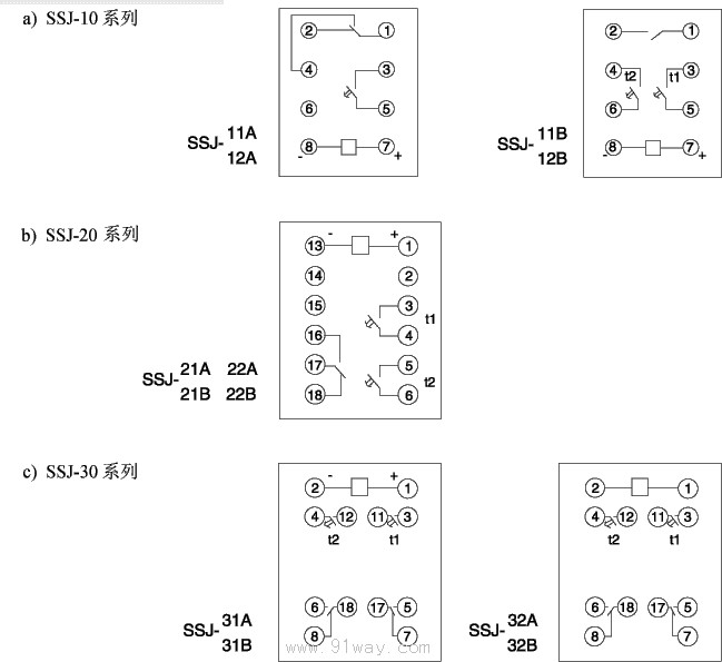
Wiring diagram behind the relay:
Relay external dimensions and opening dimensions:
See Figure 1 in the general structural system for the structure of 10Ł»
See Figure 3 in the general structural system for the 20 structureŁ»
See Figure 7 in the general structural system for the 30 structure.
Ordering instructions:
When placing an order, the relay model specifications, rated voltage, wiring method, and order quantity must be specified. If the user requests to deliver goods in sliding contact mode, the relay can provide a set of delay contacts and a set of sliding contacts. If it is required to return after a certain period of time for the sliding contact to close, special instructions must be made when ordering, and the duration of the sliding contact's closure must be specified


