Purpose:
The JSJ series static AC power-off delay relay is used in relay protection and automation circuits for AC operation, as a time element for delayed return after AC instantaneous action power-off. The relay can replace the DSJ-10 series electromagnetic time relay produced by Acheng Relay Factory. Since the wiring form of the two is the same, there is no need to change any wiring, and this relay can be directly replaced.
Relay model name:
There are four types of JSJ series relays according to their structure:
The JSJ-1 relay adopts an upward protruding fixed structure for the housing structure, and its external dimensions and installation hole dimensions are shown in Figure 1 of the general structural system;
The JSJ-2 relay adopts a protruding plug-in structure for the housing structure, and its external dimensions and installation hole dimensions are shown in Figure 3 of the general structural system;
The JSJ-3 relay adopts a Xuji embedded plug-in structure for its housing structure, and its external dimensions and installation hole dimensions are shown in Figure 7 of the general structural system.
The JSJ-4 relay adopts an modular insertion structure, as shown in the first half of the sample.
Working Principle:
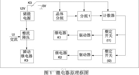
The principle block diagram of the relay is shown in Figure 1. As shown in the figure, the relay consists of a crystal oscillator, a frequency divider, a setting switch, a driving circuit, and a power supply circuit. When the rated point voltage is applied to the relay, the internal instantaneous relay and two delay relays of the relay act instantaneously, the contacts switch, and the power circuit and timing circuit are in a power-off state to improve the anti-interference performance of the relay. When the input voltage drops significantly or completely disappears, the instantaneous relay returns instantly (the two delay execution relays are still in action), and the contacts also return instantly, connecting the energy storage power supply to the timing circuit. The crystal oscillates to generate a clock pulse, which is divided into 10ms. The counter counts the timing pulse, and when the counted pulse number matches the set switch value, it drives the execution relay to return, completing the function of delayed return after power failure.
Usage:
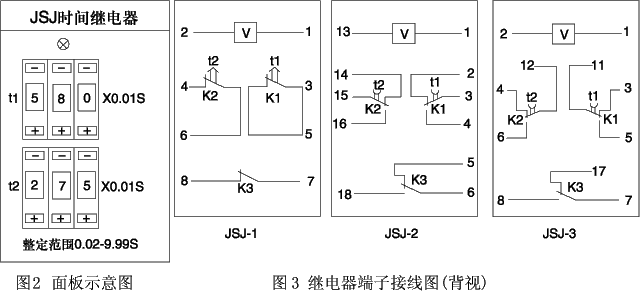
The relay panel diagram is shown in Figure 2. The upper three digit switch in the diagram sets the delay return time t1 of relay K1, and the lower three digit switch sets the delay return time t2 of relay K2. Multiplying the three digit switch by 0.01S is the time setting value. For example, if the three digit setting is 580, the time setting value is 580 ˇÁ 0.01S=5.8S. The setting values of t1 and t2 can be equal or not equal.
Main technical parameters:
6.1 Rated voltage: AC 380, 220, 110, 100V.
6.2 Rated frequency: 50HZ or 60HZ.
6.3 Ensure that the voltage required for reliable energizing of relay contacts is not greater than 80% of the rated voltage.
6.4 Ensure that the reliable power-off return voltage of the relay is not less than 10% of the rated voltage.
The delay error of relay power-off delay return under rated voltage shall not exceed 0.1% of the setting value+10ms within the setting range.
6.6 The variation of relay power-off delay under rated voltage shall not exceed 0.1% of the rated value+10ms. Variation refers to the difference between the maximum and minimum values of the relay measured five times at the same time setting point.
The contact points for the delayed return of 6.7 can be independently set, with a time setting range of 0.02-99.99 seconds, and the delay setting values can be different or the same.
6.8 The power consumed by the relay at rated voltage shall not exceed 4VA.
6.9 The relay is allowed to withstand 110% of the rated voltage for a long time.
6.10 The relay has a contact breaking capacity of 30W in a DC inductive circuit with a voltage not exceeding 250V and a current not exceeding 1A (time constant T=5 ˇŔ 0.75ms), and a contact breaking capacity of 150VA in an AC circuit with a voltage not exceeding 250V, a current not exceeding 1A, and a power factor COSO=0.4 ˇŔ 0.1.
6.11 The effective voltage between each circuit of the relay and the exposed non charged metal parts should be able to withstand 2kV, and the input circuit and contacts should be able to withstand 1kV, 50HZ AC voltage. After a 1-minute experiment, there should be no insulation breakdown or flashover phenomenon.
6.12 The relay can operate reliably within the temperature range of -10 ˇă C to 40 ˇă C.
6.13 Relay has a mechanical lifespan of 105 times and an electrical lifespan of 104 times.
6.14 Relay weight: approximately 0.5kg.
Wiring diagram behind the relay:
The wiring terminal diagram of the relay is shown in Figure 3. The contacts in the diagram are the state after the relay loses power. When the rated AC voltage is applied, the instantaneous contact K3, the contact K1 with a delay time of t1, and the contact K2 with a delay time of t2 all act simultaneously. At this time, the contact state is opposite to that shown in Figure 3. When the applied voltage suddenly loses power (voltage), the instantaneous contact K3 immediately returns, and the delayed contact K1 returns after a delay of t1 after power failure. Similarly, the delayed contact K2 returns after a delay of t2 after power failure. The contact state after return is shown in Figure 3.
JSJ series AC power-off delay relay ordering requirements:
7.1 Relay model and name;
7.2 Rated voltage;
7.3 Order quantity.