
| Product nameŁş | BFL-2B type negative sequence current relay | ||||||
| specificationŁş |  |
||||||
| CategoryŁş | low-voltage electrical apparatus -- current relay | ||||||
| PriceŁş | factory price | ||||||
| BrandŁş | |||||||
| Place of OriginŁş | China | ||||||
| Available QuantityŁş | batch | ||||||
| delivery cycleŁş | Spot goods (or inquire by telephone) | ||||||
|
|||||||
Purpose:
BFL-2B negative sequence current relay is used in the relay protection circuit of generators and transformers as a starting element to reflect the negative sequence component of fault current in case of asymmetric short circuit.
Working Principle:
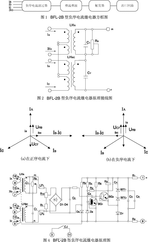
2.1 The block diagram is shown in Figure 1.
2.2 The operating principle of the relay is described as follows:
Negative sequence current filter: It consists of two converters LHA and LHBC without air gaps, capacitors C1 and C7, and potentiometer R9. The wiring diagram is shown in Figure 2.
The voltage (UR9) on R9 is proportional to the A-phase current and has a phase that is essentially the same; The voltage on C7 (UC7) is directly proportional to the difference in BC phase current, with a phase lag of 90. The BC phase adopts capacitor (C7) phase shifting, which has the main advantage of a good output voltage waveform (basically a sine wave), thus reducing the unbalanced voltage of the negative sequence current filter during system oscillation.
In the case of positive sequence current, the voltage generated by the LHA secondary current ia on potentiometer R9 is in phase with the A-phase current IA, and the voltage generated by the LHBC secondary current ibc on capacitor C7 lags behind the BC phase current by 90. If UR9 and UC7 are made equal in size, the output voltage U1mn of the filter is close to zero, U1mn=UR9+UC7 ˇÖ 0, as shown in the vector diagram in Figure 3 (a). C1 is used to compensate for angular errors caused by iron loss.
In the case of negative sequence current, the voltages UR9 and UC7 on potentiometer R9 and capacitor C7 are equal in magnitude and direction. The output voltage of the filter (U2mn) is twice UR9, where U2mn=UR9+UC7 ˇÖ 2UR9. The vector diagram is shown in Figure 3 (b).
In order to avoid the output of the filter when there is zero sequence component in the fault current, a 3IO winding is added to the LHA, with 1/3 of the turns of the A-phase winding, connected to the zero line of the current transformer; LHBC reflects the difference in BC phase current and is not affected by zero sequence current.
Transistor execution circuit:
The output voltage of the filter is applied to the trigger after passing through the bridge rectifier (D1-D4) and the impedance capacitance filter circuit (C2, R2). Under normal circumstances, BG1 is conductive, BG2 is conductive, and the actuator CJ does not operate. When an asymmetric short circuit occurs, the filter has an output voltage. When it reaches the set value, the trigger flips, that is, BG1 is conductive, BG2 is conductive, and the actuator CJ operates. Adjusting potentiometer R10 can change the setting value of the relay.
The principle wiring diagram of BFL-2B negative sequence current relay is shown in Figure 4.
Main technical parameters:
3.1 AC rated values: 5A, 1A, 20Hz.
3.2 DC rated voltage: 220V, 110V, 48V.
3.3 Negative sequence operating current adjustment range: 1-6A (rated 5A), 0.1-1A (rated 1A) continuously adjustable, with an operating value variation of no more than 6%.
3.4 Relays are allowed to pass 1.1 times the rated current for a long time.
3.5 Power consumption: Under rated current, the power consumption of each phase in the relay AC circuit shall not exceed 2VA. The power consumption of the DC circuit shall not exceed 6W at 220V, 4W at 110V, and 2W at 48V.
3.6 DC power supply variation: allowed to vary within the range of 80-110% at 220V and 110V; At 48V, it is allowed to vary within the range of 90-110%, and the relay should be able to work normally.
3.7 Temperature Influence: When the ambient temperature changes within the range of -10 ˇć to+50 ˇć, the difference between the negative sequence operating current at any set point of the relay and the negative sequence operating current at temperature+20 ˇć shall not exceed ˇŔ 10% of the latter.
3.8 Contact Form: One set of dynamic contact points.
3.9 Contact breaking capacity: In DC inductive load circuits with voltage not exceeding 220V and current not exceeding 0.2A (time constant not exceeding 5 ˇÁ 10-3s), the breaking capacity is 25W; in AC circuits, it is 300VA.
3.10 Electrical lifespan: 5000 cycles.
3.11 Weight: Approximately 1.3kg.
Wiring diagram behind the relay:
The BFL-2B negative sequence current relay has a protruding insertion structure (T-shaped).
The appearance and installation dimensions of BFL-2B negative sequence current relay are shown in Figure 4 of the universal structural system.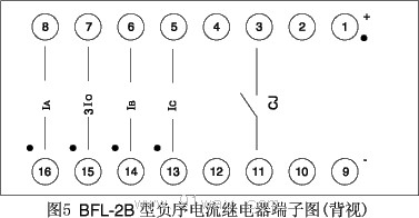
Ordering instructions:
4.1 Relay name, model, and quantity.
4.2 DC rated voltage.
4.3 AC rated current.
HomeŁüQuality CommitmentŁüOrderingŁüPayment methodŁüproduct deliveryŁüsupportŁüDisclaimerŁüContact Us
Copyright®2011 www.91way.com Copyright.
PhoneŁş+86-21-66770508 +86-13916500500 FaxŁş+86-21-66108310
Email:91way@163.com Wechat:40606422
»¦ICP±¸2021005791şĹ ![]() »¦ą«Íř°˛±¸31010702003255şĹ
»¦ą«Íř°˛±¸31010702003255şĹ