Purpose:
This relay is used in power system directional protection wiring as a power directional component. BG-12B relay is used for phase to phase short circuit protection. BG-13B relay is used for grounding protection.
Working Principle:
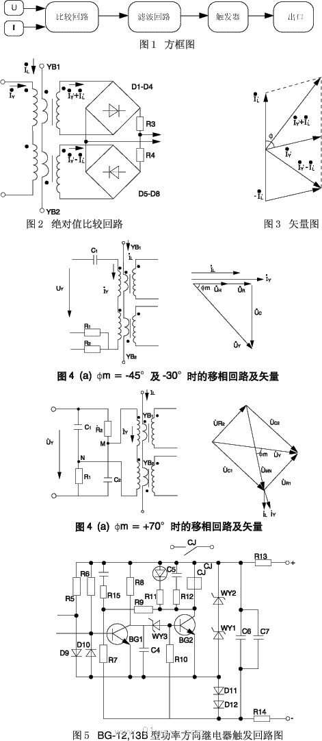
2.1 The block diagram is shown in Figure 1.
2.2 Action principle
Comparison circuit: constructed using the principle of absolute value comparison, the working circuit is composed of transformer YB1 and rectifier bridges D1-D4, and the braking circuit is composed of transformer YB2 and rectifier bridges D5-D6. The primary of transformers YB1 and YB2 are connected to currents IY and IL, respectively. Due to the same polarity series connection of the voltage winding of YB1 and the voltage winding of YB2, the current winding of YB1 and the current winding of YB2 are connected in reverse polarity series (as shown in Figure 2). Transformer YB1 is rectified by rectifiers D1-D4 and D5-D8, and then compared. The vector diagram is shown in Figure 3, and the phase difference between IL and IY is:
When -90. < o < 90ˇŁ When IY,+IL,>IY, - IL, the relay acts.
When 90. ˇÜ o ˇÜ 270ˇŁ When IY,+IL, ˇÜ IY, - IL, the relay does not operate.
This comparison circuit has the highest sensitivity when the currents IY and IL are in phase, so the maximum sensitivity is 0. IY is the current in the voltage coil, in order to achieve the maximum sensitive angle between the required protection voltage and current (phase protection is -45, -30, ground protection+70), a phase shifting circuit needs to be added outside the voltage coil to make the current IY differ from the voltage UY that generates it by an appropriate phase. The phase shift circuit and vector diagram are shown in Figures 4 (a) and 4 (b).
Filter circuit:
Using LC and a "T" - shaped filtering circuit, the signal output by the comparison circuit is pulsating DC. After passing through the LC filtering circuit, the DC signal is given to the trigger circuit;
Trigger circuit:
A collector base coupled monostable trigger consisting of two transistors, with an output component of a reed relay as shown in Figure 6.
When there is no signal input, transistor BG1 conducts, capacitor C4 is not charged, regulator WY3 is turned off, transistor BG2 is turned off, capacitor C4 is charged, regulator WY3 breaks down, transistor BG2 conducts, the output component operates, and D13 lights up. In order to eliminate contact jitter and protect transistor BG2, an RC circuit is connected in parallel at both ends of the relay coil.
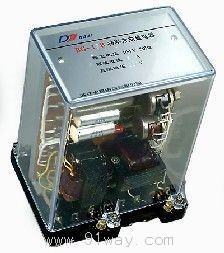
The BG-12 and 13b power direction relays are of the protruding plug-in type (T) structure with a transparent housing.
The triggering circuit diagram of BG-12 and 13b power direction relays is shown in Figure 5.
The appearance and installation dimensions of the BG-12 and 13b power direction relays are shown in Figure 4 of the universal structural system.
Main technical parameters:
3.1 AC rated value: 110V, 50Hz.
3.2 AC rated current: 5A, 1A.
3.3 DC rated voltage: 220V, 110V, 48V.
3.4 Power consumption: The AC voltage circuit shall not exceed 3VA, the AC current circuit shall not exceed 1VA, the DC 220V shall not exceed 6W, the 110V shall not exceed 4W, and the 48V shall not exceed 2W.
3.5 Contact performance: The contact breaking capacity of the DC inductive circuit relay with a voltage not exceeding 250V, current not exceeding 0.5A, and time constant of 5 ˇŔ 0.75ms is 20W, and the electrical life is 104 times.
3.6 Maximum sensitivity angle of relay, at rated value: BG-12B type -30 ˇăˇŔ 5 ˇă, -45 ˇăˇŔ 5 ˇă; BG-13B type+70 ˇăˇŔ 5 ˇă.
3.7 Relays should not exhibit current creep when subjected to 0-10 times the rated DC voltage and voltage creep when subjected to 1.1 times the rated AC voltage.
3.8 At the maximum sensitivity angle and rated current, the minimum operating voltage of the relay shall not exceed 1V.
When the DC rated voltage is separately connected or disconnected, the relay should not malfunction. When the rated voltage of 220V and 110V DC varies within the range of 80-110% of the rated value, or when the rated voltage of 48V DC varies within the range of 90-110% of the rated value, the relay can work normally.
3.10 Action time: When the maximum sensitivity angle is 4 times the action power (rated voltage of 4V), the relay action time shall not exceed 0.03s.
Ordering instructions:
Please indicate the product model, name, and quantity.