
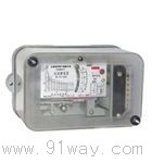
| Product nameŁş | GL-20 series current relay | ||||||
| specificationŁş |  |
||||||
| CategoryŁş | low-voltage electrical apparatus -- overcurrent relay | ||||||
| PriceŁş | factory price | ||||||
| BrandŁş | |||||||
| Place of OriginŁş | China | ||||||
| Available QuantityŁş | batch | ||||||
| delivery cycleŁş | Spot goods (or inquire by telephone) | ||||||
|
|||||||
|
relay model |
rated current (A) |
Setting value | ||
|
Action current of sensing element (A) |
ˇń Action time (S) |
ˇń Electromagnetic component action Current multiplier | ||
|
GL-21ŁŻ10 GL-21ŁŻ5 |
ten five |
4Ł»5Ł» 6Ł»7Ł» 8Ł»9Ł» ten 2Ł»2.5Ł» 3Ł»3.5Ł» 4Ł»4.5Ł» five |
0.5Ł» lŁ»2Ł» 3Ł»4 |
2Ł»4Ł» 6Ł»8 |
|
GL-22ŁŻ10 GL-22ŁŻ5 |
ten five |
4Ł»5Ł» 6Ł»7Ł» 8Ł»9Ł» ten 2Ł»2.5Ł» 3Ł»3.5Ł» 4Ł»4.5Ł» five |
2Ł»4Ł» 8Ł»12Ł» sixteen |
2Ł»4Ł» 6Ł»8 |
|
GL-23ŁŻ10 GL-23ŁŻ5 |
ten five |
4Ł»5Ł» 6Ł»7Ł» 8Ł»9Ł» ten 2Ł»2.5Ł» 3Ł»3.5Ł» 4Ł»4.5Ł» five |
2Ł»3Ł» four |
2Ł»4Ł» 6Ł»8 |
|
GL-24ŁŻ10 GL-24ŁŻ5 |
ten five |
4Ł»5Ł» 6Ł»7Ł» 8Ł»9Ł» ten 2Ł»2.5Ł» 3Ł»3.5Ł» 4Ł»4.5Ł» five |
8Ł»12Ł» sixteen |
2Ł»4Ł» 6Ł»8 |
|
GL-25ŁŻ10 GL-25ŁŻ5 |
ten five |
4Ł»5Ł» 6Ł»7Ł» 8Ł»9Ł» ten 2Ł»2.5Ł» 3Ł»3.5Ł» 4Ł»4.5Ł» five |
0.5Ł» 1Ł»2Ł» 3Ł»4 |
2Ł»4Ł» 6Ł»8 |
|
GL-26ŁŻ10 GL-26ŁŻ5 |
ten five |
4Ł»5Ł» 6Ł»7Ł» 8Ł»9Ł» ten 2Ł»2..5Ł» 3Ł»3.5Ł» 4Ł»4.5Ł» five |
8Ł»12Ł» sixteen |
2Ł»4Ł» 6Ł»8 |
When operating at 10 times the current
The ratio of the operating current of electromagnetic components to the operating current of inductive components.
3.2 The relay coil is allowed to withstand 110% of the rated current in the long term.
3.3 The return coefficient of the sensing element should not be less than 0.85 for GL-21 and 22 relays, and not less than 0.85 for GL-23, 24, 25, and 26 relays
The relay should not be less than 0.8.
When the current is equal to the operating current of the sensing element, the power consumption of the relay shall not exceed 15VA.
The on/off capacity of 3.5 contacts.
3.5.1 GL-21ˇ˘ The 22 type dynamic contact and GL-23, 24 type dynamic contact can be connected for a long time when the voltage is not greater than 220V
DC or AC 5A, but when disconnecting the connected circuit, other contacts should be used. For example, using auxiliary contacts of the oil switch.
GL-21ˇ˘ The 22 type dynamic breaking contact and GL-23, 24 type dynamic breaking main contact can disconnect AC 2A when the voltage is not greater than 220V. If the controlled circuit is powered by an inverter and connected in parallel with the relay contact, and the total impedance is not greater than 4 ¦¸ when the current is 4A, then the relay contact can be shunted and disconnected when the current in this circuit reaches 50A.
3.5.2 GL-23ˇ˘ The 24 and 26 type dynamic signal contacts can disconnect or connect DC 0.2A or AC lA when the voltage is not greater than 220V.
3.5.3 GL-25ˇ˘ Type 26 main contact, when the controlled circuit is powered by an inverter and its impedance is not greater than 4.5 ¦¸ at a current of 3.5A, the main contact can shunt and disconnect the circuit when the current is not greater than 150A.
3.6 The dielectric strength of each circuit of the relay can withstand alternating current for non charged metal parts and between circuits that are not electrically connected
50HzŁ¬ Voltage of 2kV, no breakdown or flashover for 1 minute.
3.7 The insulation resistance of each circuit of the relay to non electrified metal parts and between circuits that are not electrically connected shall be measured with a 500V megohmmeter and shall not be less than 300M ¦¸.
The weight of the 3.8 relay shall not exceed 3.1kg.
The shape and installation hole size of the 3.9 relay are shown in Figures 1, 2, and 3, respectively.
a) Pre board wiring
b) Rear wiring of the board
GL-20 series current relay
HomeŁüQuality CommitmentŁüOrderingŁüPayment methodŁüproduct deliveryŁüsupportŁüDisclaimerŁüContact Us
Copyright®2011 www.91way.com Copyright.
PhoneŁş+86-21-66770508 +86-13916500500 FaxŁş+86-21-66108310
Email:91way@163.com Wechat:40606422
»¦ICP±¸2021005791şĹ ![]() »¦ą«Íř°˛±¸31010702003255şĹ
»¦ą«Íř°˛±¸31010702003255şĹ