|
Product name: |
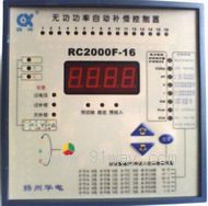
RC2000F Zero crossing switching phase separation compensation controller (combination of co compensation and sub compensation)
|
|
specification: |
|

 Zoom in on the image Zoom in on the image |
|
Category: |
low-voltage electrical apparatus
-- Compensation equipment |
|
Price: |
factory price |
|
Brand: |
Shanghai |
|
Place of Origin: |
China |
|
Available Quantity: |
batch |
|
delivery cycle: |
Spot goods (or inquire by telephone) |
|
| |
Shanghai Beiyuan Industry and Trade Co.,Ltd
+86-21-66770508
+86-13916500500 |
 91way@163.com 91way@163.com
 13916500500(Wechat) 13916500500(Wechat)
|
|
|
|
RC2000F Zero crossing switching phase separation compensation controller (combination of co compensation and sub compensation)Detailed product description:

The RC2000F series intelligent harmonic phase separation compensation controller uses a high-speed and high-performance microprocessor as the core device to simultaneously sample 3-phase voltage and 3-phase current signals, and provides 6 compensation schemes for phase separation (Y) and common compensation (△), as well as 12 switching coding schemes. Users can freely choose by modifying the control parameters, and once the control parameters are modified, they will be permanently saved without losing data in case of power failure. The switching of the capacitor bank is controlled by a combination of fundamental power factor and fundamental reactive power, which ensures stable switching without oscillation and has a certain resistance to harmonic interference. A function that can only be achieved by multiple old models, suitable for reactive power compensation control in AC power systems with unbalanced loads below 45Hz-65Hz and 0.4Kv.
2. Technical data
Rated operating frequency: 45Hz-65Hz Display power factor: lag 0.001- lead 0.01
Undervoltage protection value 170V static output contact capacity per circuit: AC 220V 7A
Sensitivity 50mA dynamic output capacity per channel: DC12V 20mA/branch
Dimensions: RC2000F-12 122mm × 122mm × 99mm Power consumption: 10VA
Dimensions: RC2000F-16 144mm × 144mm × 87mm Display: 4-digit red digital tube Hole size: RC2000F-12 112mm × 112mm Protection level: IP40 shell Hole size: RC2000F-16 138mm * 138mm Connection method: socket terminal screw fixation
Installation Method: RC2000F-12 Embedded Installation Hook Attachment Fixed
Installation method: RC2000F-16 embedded installation with inverted gear accessories fixed or rail mounted
3. RC2000F zero crossing switching phase separation (combined compensation and compensation) compensation controller output code
Generally, traditional controllers only have one encoding method, which is equal capacity (1:1:1...: 1) cyclic switching. The value of the capacitive reactive power to be compensated by the power grid is often continuous and not graded. Due to hardware limitations, the capacitive reactive power provided by the compensation device is usually limited to a few levels. This is a supply-demand contradiction, which is most prominent when the system load is relatively small. Here is an example: For example, a user has a 315KVA transformer with a total compensation capacity of 100Kvar, using a total of 5 20Kvar capacitor banks. The controller uses the commonly used JKG (L) in the market The control physical quantity of this controller is power factor. The target power factor input threshold is lag 0.92, and the cut-off threshold is lag 0.99. At a certain time in the evening, it was found that the system power factor was lag 0.60, the apparent power was 12.5KVA, and the inductive reactive power was 10Kvar. The controller kept switching actions. The reason for this is that the capacity of a single capacitor group (20Kvar) is much larger than the required compensation capacity of the system (10Kvar). When the controller does not input the capacitor group, the power factor of the system is 0.60. According to the control principle of JKG (L) type controller, when the system power factor is lower than the target power factor, the controller must input the capacitor group. After the capacitor group is input, due to compensating for the capacitive reactive power of 10Kvar, the compensated power factor changes from inductive 0.60 to capacitive 0.60 The cut-off power factor threshold of the type controller is a lag of 0.98, so the controller needs to cut off the capacitor bank that has just been put into operation, which repeatedly operates back and forth. This is called switching oscillation in professional terms, and its drawbacks are twofold: firstly, frequent and meaningless switching actions greatly shorten the service life of the capacitor bank and AC contactor. Secondly, although compensation devices are installed in the power system, the expected compensation effect cannot be achieved. Most users will encounter the above phenomena, but the difference is that the situation varies from mild to severe. This is an unavoidable problem for every user. To solve the above problems, we believe that three points can be achieved: firstly, the physical quantity of the controller's switching control must be taken as zero
The practice of matching capacitor capacity to adapt to changes in grid load size is referred to as output coding in this manual. Since it is coding, the size of the capacitor capacity cannot be arbitrarily given, and it should comply with certain rules. This controller provides 11 capacitor capacity ratio size matching schemes, which are:
Pr-1 => 1:1:1:1:1:…:1 Pr-2 => 1:2:2:2:2:…:2
Pr-3 => 1:2:4:4:4:…:4 Pr-4 => 1:2:4:8:8:…:8
Pr-5 => 1:1:2:2:2:…:2 Pr-6 => 1:1:2:4:4:…:4
Pr-7 => 1:1:2:4:8:…:8 Pr-8 => 1:2:3:3:3:…:3
Pr-9 => 1:2:3:6:6:…:6 Pr-10=> 1:1:2:3:3:…:3
Pr-11=>1:1:2:3:6:...: 6 Pr-12=>Cut in order
We use the RC2000F controller to solve the problem in the above example
Based on the characteristics of the example power grid parameters, we chose the Pr-3 coding scheme. According to the proportional relationship between the total compensation capacity and the capacity of the Pr-3 coding scheme, the first circuit takes 5Kvar, the second circuit takes 10Kvar, the third circuit takes 20Kvar, the fourth circuit takes 20Kvar, the fifth circuit takes 20Kvar, and the sixth circuit takes 20Kvar. There are a total of six capacitor banks. When the power grid requires 10Kvar, the controller only needs to activate the second circuit. When 15Kvar is required, only the first and second circuits need to be activated simultaneously. When 20Kvar is required, only the third circuit needs to be activated. For example, if 1.3 sets of capacitors have already been put into operation and the load changes, and 15KVAR is needed again, the controller will simultaneously issue a command to cut off the first set and put in the fourth set of capacitors, so as to maintain the target power at the optimal state and achieve no compensation effect. The RC2000F can automatically complete the selection of all required input and removal capacities. Due to the use of reactive power to control the switching of capacitor banks in RC2000F, there is no problem of switching oscillation.
 Related Products:
- Related articles:
