
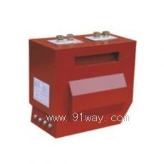
| Product name: | LZZB1-10,LZZB1-10GY type current transformer | ||||||
| specification: |  |
||||||
| Category: | High voltage electrical appliances -- 10KV current transformer | ||||||
| Price: | factory price | ||||||
| Brand: | |||||||
| Place of Origin: | China | ||||||
| Available Quantity: | batch | ||||||
| delivery cycle: | Spot goods (or inquire by telephone) | ||||||
|
|||||||
LZZB1-10, LZZB1-10GY type current transformer
1. Model and its meaning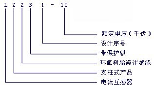
2. Product standards
The product performance complies with the GB1208-1997 national standard, DL/T 725-2000 power industry standard, and IEC185 standard.
3. Structure and specifications
This type of current transformer has a pillar structure and is fully enclosed and cast with epoxy resin. Good resistance to dirt and moisture. This product has two secondary windings. The accuracy limit coefficient of the first secondary winding is 5P20, with an accuracy of 0.2 (or 0.5) level, which can be used for protection or shared for protection and measurement. The accuracy of the second secondary winding is 0.1 level, and it also meets the requirement of 0.2S level, which can be used for measurement or shared by measurement and measurement.
This type of current transformer has multiple transformation ratios: 30/5A (1A), 40/5A (1A), 50/5A (1A), 75/5A (1A), 100/5 A(1A)、150/5A(1A)、200/5A(1A)、300/5A(1A)、400/5A(1A)、 600/5A(1A)、750/5A(1A)、800/5A(1A)、1000/5A(1A)、1200/5A(1A)、 1500/5A(1A)、1600/5A(1A)、2000/5A(1A) varied. The external dimensions of this product are shown in Figure 1 and Figure 3, and the dimensions of the primary winding terminal are shown in Figure 2 and Figure 4.
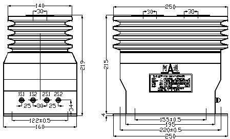
Figure 1 Outline dimension diagram of products below 1200A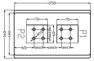
Figure 2 Size diagram of primary winding terminal block for products below 1200A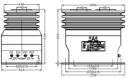
Figure 3 Outline dimension diagram of products above 1500A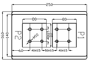
Figure 4 Dimension diagram of primary winding terminal for products above 1500A
4 Product Rating and Technical Parameters
4.1 Rated voltage: 10kV
4.2 Maximum operating voltage: 12kV
4.3 Rated frequency: 50Hz
4.4 Rated primary current: 30 A、40A、50A、75A、100A、150A、200A、300A、400A、600A、750A、800A、1000A、1200A、1500A、1600A、2000A。
4.5 Rated secondary current: 5A or 1A.
4.6 Rated output: 25VA, load power factor of 0.8-1.
4.7 Accuracy level, accuracy limit factor (ALF), and instrument security factor (FS):
4.7.1 First secondary winding (for protection and measurement) 1S1-1S2
The accurate limit coefficients and accuracy levels at various rated outputs are shown in Table 1, and the power factor of the load is COS Φ=0.8-1.
Table 1
|
primary current |
Accuracy limit factor (ALF) of 1S1-1S2 at the following rated outputs |
1S1-1S2 accuracy level | |||
|
10VA |
15VA |
20VA |
25VA |
10VA-25VA | |
|
30-800A |
5P20 |
5P15 |
5P10 |
5P10 |
Level 0.5 |
|
1000A |
5P25 |
5P20 |
5P15 |
5P15 |
Level 0.2 |
|
1200A |
5P25 |
5P20 |
5P20 |
5P15 |
Level 0.2 |
|
1500A |
5P25 |
5P20 |
5P20 |
5P15 |
Level 0.2 |
|
1600A |
5P30 |
5P20 |
5P20 |
5P15 |
Level 0.2 |
|
2000A |
5P30 |
5P25 |
5P20 |
5P20 |
Level 0.2 |
| one |
Accuracy level and instrument security factor of 2S1-2S2 at the following rated outputs | |||
|
Rated output VA |
10VA |
15VA |
20VA |
25VA |
|
accuracy level |
zero point one |
zero point one |
zero point one |
0.2S |
|
Instrument security factor (FS) |
ten |
ten |
ten |
ten |
|
Rated transformation ratio |
Rated short-time thermal current (kA) |
Rated dynamic stability current (kA) |
Weight (kg) |
|
30-100/5A(1A) |
fifteen |
thirty-seven point five |
≤ 20 |
|
150/5A(1A) |
twenty-two point five |
fifty-six |
≤ 20 |
|
200/5A(1A) |
thirty |
seventy-five |
≤ 20 |
|
300-400/5A(1A) |
forty-five |
one hundred and twelve point five |
≤ 20 |
|
600-800/5A(1A) |
sixty-three |
one hundred and twenty |
≤ 20 |
|
1000-1200/5A(1A) |
seventy-five |
one hundred and thirty |
≤ 20 |
|
1500-2000/5A(1A) |
ninety |
one hundred and forty |
≤ 20 |
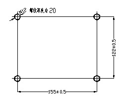
Figure 5 Installation hole size diagram without installation base plate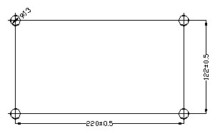
Figure 6 Installation hole size diagram with installation base plate
5.2 Use
Before use, the polarity of the secondary winding wiring should be checked to ensure that 1S1, 2S1, and P1 have the same polarity. When the primary current flows into the transformer from P1 and flows out from P2, the secondary current flows out from 1S1 and 2S1, passes through the secondary load, and then flows back to the transformer from 1S2 and 2S2. When there is current in the primary winding during operation, the secondary winding must not be open circuited, otherwise dangerous high voltage may be generated between the terminals of the secondary winding
Home|Quality Commitment|Ordering|Payment method|product delivery|support|Disclaimer|Contact Us
Copyright®2011 www.91way.com Copyright.
Phone:+86-21-66770508 +86-13916500500 Fax:+86-21-66108310
Email:91way@163.com Wechat:40606422
沪ICP备2021005791号 ![]() 沪公网安备31010702003255号
沪公网安备31010702003255号