
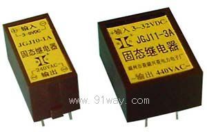
| Product nameŁş | JGJ10,JGJ11 Direct insertion horizontal single-phase AC solid-state relay | ||||||
| specificationŁş |  |
||||||
| CategoryŁş | low-voltage electrical apparatus -- solid state relay | ||||||
| PriceŁş | factory price | ||||||
| BrandŁş | |||||||
| Place of OriginŁş | China | ||||||
| Available QuantityŁş | batch | ||||||
| delivery cycleŁş | Spot goods (or inquire by telephone) | ||||||
|
|||||||
| JGJ10 (formerly JGX0J) | JGJ11 (formerly JGX1J) | ||
| lose enter ginseng number |
control voltage | 3ˇ«9VD C12ˇ«32VDC | |
| control the current | 5ˇ«28mA 6ˇ«25mA | ||
| starting current | ˇÝ6mA | ||
| Turn off voltage | ˇÜ1VDC | ||
| On-off time | ˇÜ15mS | ||
| lose go out ginseng number |
load voltage | 24ˇ«240VAC 24ˇ«440VAC | |
| Maximum load current | 1A 3A | ||
| On state pressure drop | ˇÜ1.5V | ||
| Off state voltage | ˇÝ400V ˇÝ800V | ||
| sex can ginseng number |
isolation voltage | ˇÝ2000V | |
| insulation resistance | ˇÝ100M¦¸ | ||
| Operating Temperature | ˇŞ25ˇ«75 ˇć | ||
| power frequency | 50/60HZ | ||
| Load current safety factor | Resistive load is taken as 2-3 times, inductive load is taken as 3-4 times | ||
| External dimensions (code) | 31ˇÁ16ˇÁ16mm3(H-1) | 33ˇÁ25ˇÁ15mm3(H-2) | |
External dimensions Installation wiring diagram: (unit: mm)
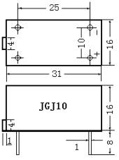
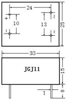
H-1 H-2
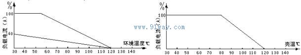
Temperature curve chart:
JGJ10, JGJ11 straight insertion horizontal single-phase AC solid state relay selection precautions:
When selecting products, different margins should be left in the current level according to the nature of the load. (For resistive loads, 2-3 times the load current can be selected. For inductive or capacitive loads, 3-4 times the load current can be selected).
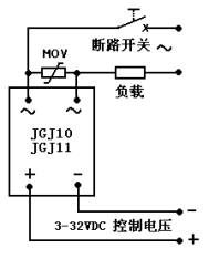
According to the relationship between load current and ambient temperature, when the ambient temperature is high or the heat dissipation conditions are poor. The current capacity should be increased. To prevent short circuit of the load during use, it is required to connect a fast circuit breaker or fast fuse corresponding to this product in series in the load circuit.
When dealing with inductive loads, a varistor should be connected in parallel at the output end to prevent damage to the thyristor during overvoltage. Selection of Varistors (MOVs): 430-470V for 240V and 680-750V for 440V.
When the input control voltage is marked as 3-32VDC and the actual load voltage is greater than 12VDC, a protective resistor should be connected in series in the control circuit, which can be determined according to the input current (8-25mA) (usually about 1.5K ¦¸/1-2W).
This model of product is naturally cooled and does not require a radiator during operation.
HomeŁüQuality CommitmentŁüOrderingŁüPayment methodŁüproduct deliveryŁüsupportŁüDisclaimerŁüContact Us
Copyright®2011 www.91way.com Copyright.
PhoneŁş+86-21-66770508 +86-13916500500 FaxŁş+86-21-66108310
Email:91way@163.com Wechat:40606422
»¦ICP±¸2021005791şĹ ![]() »¦ą«Íř°˛±¸31010702003255şĹ
»¦ą«Íř°˛±¸31010702003255şĹ