The SRMB1 surge protector (hereinafter referred to as the "protector") is suitable for use in power supply systems (or communication systems) such as TT, IT, TN-S, TN-C with AC 50/60Hz and rated voltage up to 380V, to protect against indirect lightning and direct lightning effects or other transient overvoltage surges.
The protector complies with GB18802.1 standard.
One Normal working conditions
1. The altitude shall not exceed 2000m;
2. Surrounding air temperature: normal range: -5 ℃ to+40 ℃, limit range: -40 ℃ to+70 ℃;
3. Atmospheric conditions: The relative humidity should be between 30% and 90% at room temperature;
4. The inclination to the vertical plane shall not exceed 5 degrees;
5. Places without significant shaking and impact vibration;
6. In a medium without explosive hazards, and without gases and dust (including conductive dust) that corrode metals or damage insulation.
II Main technical parameters and performance
The main technical parameters of the protector are shown in Table 1 and Table 2, and the model of the zero ground protection module is SRMB1-NPE.
|
model
specification |
grid operation
voltage
Ue V |
voltage protection
level
Up kV |
Maximum discharge
current
Imax kA |
Nominal discharge
current
In kA |
leakage current
Ic |
response time
t ns |
|
SRMB1 Ⅱ-40 |
220/380 |
1.5/2.0 |
sixty |
forty |
< 1mA
|
< 25 |
|
SRMB1 Ⅱ-20 |
1.2/1.8
|
forty |
twenty |
|
SRMB1 Ⅱ-10 |
twenty |
ten |
|
SRMB1 Ⅱ-5 |
ten |
five |
|
SRMB1-NPE |
one point two |
forty |
twenty |
< 10μA |
< 100 |
Note: (1) SPD series with Uc=140V, 320V, 385V, 550V have special specifications.
(2) The NPE protection module with Uc=420V is a special specification.
|
type |
Operating voltage of power grid
Ue V |
Maximum continuous operating voltage
Ue V
|
Voltage protection level Up kV |
grounding system |
|
In=20、10、5kA |
In=40kA |
|
1P |
two hundred and twenty |
420/275
|
1.8/1.2
|
2.0/1.5 |
TN-C、IT |
|
2P |
TT、TN-S、IT |
|
3P |
three hundred and eighty |
four hundred and twenty |
one point eight |
two |
TN-C、IT |
|
4P |
TT、TN-S、IT |
|
1P+N |
two hundred and twenty |
420/275 |
one point two |
one point five |
TT、TN-S、IT
|
|
3P+N |
three hundred and eighty |
2. Failure to disconnect device
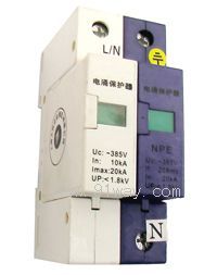
The module of the protector is equipped with a failure disengagement device. When the protector fails due to overheating or breakdown, the failure disengagement device can automatically disconnect it from the power grid and provide an indication signal. When the protector is normal, the label displays green, and after failure disengagement, the label displays red.
3. Basic parameters
(1) Maximum continuous operating voltage Uc: A.C.140275230385420550V;
(2) Protection level: B, C, D;
(3) Protection level Up: 1.2, 1.5, 1.8, 2.0kV;
(4) Maximum discharge current (8/20 μ S) Imax: 10, 20, 40, 60kA;
(5) Nominal discharge current (8/20 μ S) In: 5, 10, 20, 40kA.
III Main structure and working principle
In a three-phase four wire system, three phase wires and one neutral wire are all connected to the grounding wire with a protector. Under normal circumstances, the protector is in a high resistance state. When the power grid experiences surge overvoltage due to lightning strikes or other reasons, the protector will immediately conduct rapidly in nanoseconds, introducing the surge overvoltage into the ground and protecting the electrical equipment on the power grid. When the surge voltage passes through the protector and disappears, the protector returns to a high resistance state, so as not to affect the normal operation of the power grid.
4 Installation
1. The protector is installed on a standard TH35-7.5 track.
2. The protector is connected by copper wire, with a cross-sectional area of: flexible wire: 2.5-16mm2; Hard wire: 2.5-25mm2. There are two wiring methods:
a) Connect the power switch to the protector, and then connect the protector to the load end. This method is suitable for distribution boxes with load currents below 100A. The cross-sectional area of the wire should be selected according to the load current.
b) From the power switch connection to the protector, and also from the power switch connection to the load end. This method is suitable for distribution boxes with a load current of 100A or more. The cross-sectional area of the wire connected to the protector is not affected by the load current, but the length must not be too long and the total length of the grounding wire must not exceed 500mm2.
3. The grounding wire should use a dual color wire of 4mm2 or more.
To prevent the failure of surge protectors from affecting the normal operation of the power grid, a 32A fuse should be connected in series to the protector connected to the L line;
Five Adjustment, use, and maintenance
1. The protector does not need to be adjusted after installation as required;
2. As long as the protector is installed properly, it can automatically protect the power grid;
3. During operation, it is necessary to regularly check whether the module label is red and observe whether the red indicator light of the fuse is on. Failure components should be replaced in a timely manner.
VI Ordering Instructions
When placing an order, the model and quantity should be indicated. For example: 4 SRMB1 II-40/2P units
2. The following documents are included with the product packaging box during shipment:
a) 1 copy of product qualification certificate (for each product)
b) 1 copy of user manual (for each product)
c) 1 copy of packing list (for each large packaging box)