
| Product name: | End type dual power automatic transfer switch | ||||||
| specification: |  |
||||||
| Category: | low-voltage electrical apparatus -- dual power switch | ||||||
| Price: | factory price | ||||||
| Brand: | |||||||
| Place of Origin: | China | ||||||
| Available Quantity: | batch | ||||||
| delivery cycle: | Spot goods (or inquire by telephone) | ||||||
|
|||||||
Model meaning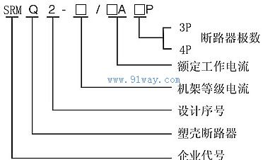
Scope and characteristics of application
The SRMQ2 automatic power switch (hereinafter referred to as the switch) is suitable for dual power supply systems with AC 50HZ rated working voltage of 380V and rated working current of 63A-225A. It can be operated automatically or manually to switch between the common power supply and the backup power supply. This toggle switch is mainly used in important occasions such as hospitals, shops, banks, chemical, metallurgical, high-rise buildings, military facilities, etc.
Normal working conditions
1. The installation altitude should not exceed 2000 meters.
2. The upper limit of the ambient temperature shall not exceed+40 ℃, the lower limit shall not be lower than -5 ℃, and the 24-hour average shall not exceed+35 ℃.
3. The relative humidity of the atmosphere should not exceed 50% when the surrounding air temperature is+40 ℃. At lower temperatures, there may be higher humidity, and temperature changes should be considered to cause condensation on the surface of the product.
4. The medium has no explosive hazard, and there is no gas or dust that can corrode or damage the insulation.
5. A place without significant shaking or impact vibration.
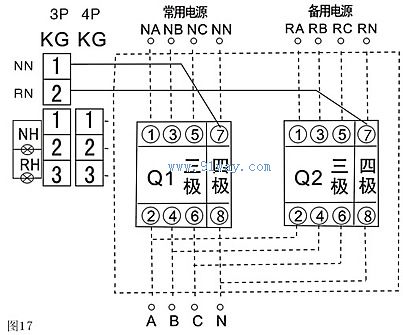
Installation and usage methods
When wiring, the common power supply N should be connected to the common power supply executing circuit breaker QN, and the backup power supply R should be connected to the backup power supply executing circuit breaker QR. When QN and QR are four wire circuit breakers, the wiring method should follow the wiring diagram, where QN and QR have 1, 3, and 5 as the three-phase (A, B, C) incoming terminals, 2, 4, and 6 as the three-phase outgoing terminals, 7 as the neutral line (N) incoming terminal, and 8 as the neutral line outgoing terminal. If a three pole circuit breaker is selected, the neutral wire NN of the common power supply (N) and the neutral wire NR of the backup power supply (R) must be connected to the three pole dedicated neutral wire terminal KG at the same time. Please refer to the wiring diagram for specific instructions. The working power supply of the dual power switch automatic controller is taken from the input terminals A and neutral wires N of circuit breakers QN and QR. If a three pole circuit breaker is selected, the neutral wires NN and NR must be connected. The dedicated neutral terminal of the three pole wiring is located between the two circuit breakers. During the installation of the automatic power switch, do not connect the original wire to the input terminal of the circuit breaker
Forgetting, breaking or short circuiting of the local controller cable.
1. Common neutral wire
2. Backup neutral wire
3. Indicator light common terminal
4. Common indicator lights
5. Backup indicator light
Home|Quality Commitment|Ordering|Payment method|product delivery|support|Disclaimer|Contact Us
Copyright®2011 www.91way.com Copyright.
Phone:+86-21-66770508 +86-13916500500 Fax:+86-21-66108310
Email:91way@163.com Wechat:40606422
沪ICP备2021005791号 ![]() 沪公网安备31010702003255号
沪公网安备31010702003255号