|
Product name: |
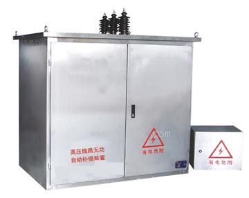
TBBWZ Series High Voltage Line Reactive Power Automatic Compensation Device
|
|
specification: |
|

 Zoom in on the image Zoom in on the image |
|
Category: |
low-voltage electrical apparatus
-- Compensation equipment |
|
Price: |
factory price |
|
Brand: |
Shanghai |
|
Place of Origin: |
China |
|
Available Quantity: |
batch |
|
delivery cycle: |
Spot goods (or inquire by telephone) |
|
| |
Shanghai Beiyuan Industry and Trade Co.,Ltd
+86-21-66770508
+86-13916500500 |
 91way@163.com 91way@163.com
 13916500500(Wechat) 13916500500(Wechat)
|
|
|
|
TBBWZ Series High Voltage Line Reactive Power Automatic Compensation DeviceDetailed product description:

The TBBWZ series high-voltage line reactive power automatic compensation device is suitable for installation on outdoor poles in 6-10kV transmission lines. As a means of improving power factor, reducing line losses, and enhancing voltage quality.
working conditions
1. Installation method: Outdoor column installation;
2. Environmental temperature: -40 ℃ to+50 ℃;
3. Altitude: ≤ 1000m:
4. Wind speed: ≤ 35m/s;
5. There is no corrosive gas or vapor around, and no conductive or explosive dust.
Main technical parameters of TBBWZ series high-voltage line reactive power automatic compensation device
1. Rated voltage: 6-10kV;
2. Rated frequency: 50Hz;
3. Compensation capacity: 30-900kvar;
4. Secondary control voltage: AC220V;
5. Main circuit power frequency withstand voltage: 42kV/mi;
6. Auxiliary circuit withstand voltage: 2.5kV/min;
7. Lightning impulse withstand voltage: 75kV;
8. Service life: Over 300000 cycles.
Product Features
1. The capacitor has built-in fuses and discharge resistors, which self discharge after power failure to ensure safe operation;
2. Capacitors can be built-in or external, with a capacity preferably configured in a 1:2 ratio, and can achieve three-level switching;
3. It can automatically switch according to voltage, power factor, reactive current, and other methods;
4. Equipped with overvoltage, undervoltage, overcurrent, and phase loss protection functions;
5. The device can be switched automatically or manually, making it convenient for users to debug and operate. Using high-voltage vacuum contactor switch to switch capacitors, it can switch frequently, has the characteristics of long service life, safety and reliability, and maintenance free;
6. Adopting advanced intelligent reactive power compensation controller as the control core, it can display various parameters of the circuit, such as current, voltage, active power, reactive power, power factor, current voltage distortion rate, harmonic content, etc. And save daily on-time data and daily statistical data for more than 200 days, up to a maximum of 800 days. The controller has the functions of "four remote" (telemetry, remote control, remote adjustment, remote signaling);
7. By using on-site and remote communication, real-time and timed calling of various power parameters, modification of control parameters, and remote switching of capacitors can be achieved. Short distance (30-50m) wireless communication can be used to achieve on-site meter reading of handheld computer data;
8. Each capacitor configuration has a minimum capacity of 50kvar and a maximum capacity of 900kvar. It can be configured as one fixed group, one automatic switching group, or two automatic switching groups.
Structural characteristics of TBBWZ series high-voltage line reactive power automatic compensation device
1. Drop out fuse, serving as both short-circuit protection and isolation switch, with the upper end connected to the high-voltage line and the lower end connected to the lightning arrester and box;
2. Lightning arrester, used for absorbing overvoltage during operation;
3. Sealed switch box, with a conduit for incoming lines at the top. Inside the box, there are voltage transformers (used for vacuum switch operation power supply and voltage protection), current transformers, and vacuum contactors. Other controllers, indicator lights, etc. are all installed inside the control box, which is isolated from the high-voltage section;
4. External capacitor type, with an outlet sleeve on the side of the box. The capacitors are distributed on one side of the box and connected to this outlet sleeve. The top of the box is covered with a rainproof cover and equipped with lifting rings for hoisting. The switch box is installed on the platform between two poles, and the control box is fixed on the poles;
5. Sampling current transformer, with a dedicated outdoor open type current transformer installed in phase A of the line.
Selection of compensation capacity and methods
If the power factor of the line before compensation is COS φ 11 and after compensation is COS φ 2, the active power of the line is P, and the compensation capacity Q (kvar)=p(), if P is the active power of the line's frequent load, COS φ 2 can be selected higher. If P is the maximum active power on the line, COS φ 2 can be selected lower. To reduce costs, a fixed compensation set should be installed on the line, with its capacity determined by the capacity of the distribution transformer on the line. The selection principle is not greater than the no-load capacity of the distribution, which is about 5-10% of the distribution transformer. Small capacity transformers with larger total capacity can be selected on the line, so that even if there is no load on the line, it will not be overloaded. If the maximum load on the line is not significantly different from the regular load, a fixed set of automatic switching can be selected. If the difference between the two is significant, two sets of automatic switching with a ratio of 1:2 can be selected, which generally meets the compensation requirements. Fixed compensation can also be installed separately, including drop out fuses, lightning arresters, and capacitors, which should generally be installed behind the load center of the line. The installation location should be selected as follows: if reactive power control is used, it should be installed at the beginning of the line, and more than 70% of the load current should flow through the sampling current transformer. If it is voltage control, it should be installed at the end of the line; Usually located 3/2 to 4/3 from the beginning of the line. Regardless of the type of control, it should be as close as possible to the load center of the line to avoid increasing line loss due to long-distance transmission of reactive power. Voltage control is commonly used in places where the voltage at the end of the line is low. If the voltage is particularly low, it is increased by overcompensation. In this case, it is generally not necessary to install expensive sampling current transformers.
Ordering Instructions
1. The voltage level of the line that needs to be compensated;
2. Provide a statistical table of active power, reactive power, maximum current, minimum current, and average current of the line within one year;
3. The layout diagram of the transformer network for this line, as well as the installed capacity of each transformer;
4. Compensation capacity and compensation method, with built-in or external capacitors;
5. Compensation combination method: automatic or automatic fixed;
6. Single pole installation or double pole installation;
7. Control mode: reactive power, voltage, time;
8. The shell is made of cold-rolled steel or stainless steel.
 Related Products:
- Related articles:
