
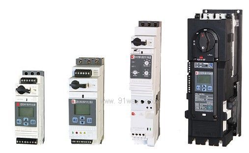
| Product name: | CB1 series control and protection switchgear | ||||||
| specification: |  |
||||||
| Category: | low-voltage electrical apparatus -- Motor protector | ||||||
| Price: | factory price | ||||||
| Brand: | Shanghai | ||||||
| Place of Origin: | China | ||||||
| Available Quantity: | batch | ||||||
| delivery cycle: | Spot goods (or inquire by telephone) | ||||||
|
|||||||
| project | technical parameters | |||||||||
| model | CB1-12 | CB1-32 | CB1-63 | CB1-125 | ||||||
| main circuit | Agreed free air heating current Ith (A) | twelve | thirty-two | sixty-three | one hundred and twenty-five | |||||
| Rated working current Ie (A) | twelve | thirty-two | sixty-three | one hundred and twenty-five | ||||||
| Usage category | AC-43 | |||||||||
| Rated working voltage Ue (V) | AC400,690/AC50Hz | |||||||||
| Rated insulation voltage Ui (V) | six hundred and ninety | eight hundred | ||||||||
| Rated impulse withstand voltage Uimp (kV) | six | eight | ||||||||
| polar number | three | |||||||||
| Rated operating short-circuit breaking capacity Ics (kA) | AC400V | fifty | one hundred and fifty | |||||||
| AC690V | four | fifteen | ||||||||
| Total cutoff time (ms) | three | |||||||||
| Intelligent controller (release device) | Rated current of release device Iet (A) | zero point six | one point four | five | twelve | eighteen | thirty-two | sixty-three | one hundred and twenty-five | |
| Set current range Ir1 (A) | 0.15~0.6 | 0.35~1.4 | 1.25~5 | 3~12 | 4.5~18 | 8~32 | 32~63 | 63~125 | ||
| Code for setting current range | R1 | R2 | R3 | R4 | S1 | S2 | T | U | ||
| The maximum rated power Pe (kW) of the controlled motor corresponding to Iet | AC400V | zero point one two | zero point three seven | one point five | five point five | seven point five | fifteen | thirty | fifty-five | |
| AC690V | zero point two five | zero point seven five | three | seven point five | eleven | twenty-two | thirty | one hundred and ten | ||
| Control characteristics | Rated control power supply voltage Us (V) | AC230/AC50Hz | ||||||||
| Maximum power consumption (W) | four | seven | ||||||||
| Action time (ms) | close | <85 | ||||||||
| disconnect | <75 | |||||||||
| Mechanical lifespan (10000 cycles) | one thousand and two hundred | five hundred | ||||||||
| Electrical lifespan (AC-43) (10000 cycles) | AC690V | four | ||||||||
| AC400V | one hundred and fifty | one hundred and twenty | one hundred | |||||||
| Operating frequency (times/h) | 1200 (load factor of 40%) | 600 (load factor of 40%) | 1200 (load factor of 25%) | |||||||
| auxiliary contact | Output quantity | ZA controller: 3NO3NC; ZL, ZP, ZM, ZF, EJ, EF, ES controllers: 1NO1NC | ||||||||
| output capacity | See sample for details | |||||||||
| Shell protection level | front panel | IP40 | ||||||||
| Wiring area | IP20 | - | ||||||||
| Note 1: When the rated working voltage is AC690V, a phase partition should be used; Note 2: At AC690V, the maximum operating currents of CB1-32 and 63 are 21A and 45A, respectively. The controller setting current Ir1 should not exceed the maximum operating current; Note 3: EJ, EF, and ES controllers are applicable to CB1-12 and 32. |
||||||||||
Home|Quality Commitment|Ordering|Payment method|product delivery|support|Disclaimer|Contact Us
Copyright®2011 www.91way.com Copyright.
Phone:+86-21-66770508 +86-13916500500 Fax:+86-21-66108310
Email:91way@163.com Wechat:40606422
沪ICP备2021005791号 ![]() 沪公网安备31010702003255号
沪公网安备31010702003255号