
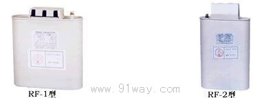
| Product name: | RF series low-voltage phase capacitor | ||||||
| specification: |  |
||||||
| Category: | low-voltage electrical apparatus -- power capacitor | ||||||
| Price: | factory price | ||||||
| Brand: | |||||||
| Place of Origin: | China | ||||||
| Available Quantity: | batch | ||||||
| delivery cycle: | Spot goods (or inquire by telephone) | ||||||
|
|||||||
Wiring method of RF series low-voltage phase in capacitor
Connect wires; Please connect the press fit terminals with holes drilled on M5. (Can be connected to 22mm press fit terminals)
Same capacitor wiring
Please fix it correctly with a firm torque of 35-40Kgf.cm.
Cover cover
Finally, cover the lid.
Scope of application
This product complies with the International Electrotechnical Commission IEC831-1988 standard.
Setting location: Indoor dedicated
Temperature range for use: -40 ℃~+45 ℃
Capacity deviation: -5%~+10%
Voltage endurance: 700VAC between terminals for 2-5 seconds, 3000VAC between all terminals and the outer box for 10 seconds
Loss rate: below 0.12%
Allowable overvoltage: below 110% of rated voltage (within 24 hours, within 8 hours)
Below 115% of rated voltage (within 24 hours and 30 minutes)
Less than 120% of rated voltage (within 1 month, within 5 minutes, twice or less)
Less than 130% of rated voltage (within 1 month, within 1 minute, twice or less)
Allowable overcurrent: below 130% of rated current
Insulation impedance: All terminals have an external impedance of over 300 Ω (500VDC)
Internal discharge resistor: below 75V after 3 minutes, equipped with safety device
Instructions for Using RF Series Low Voltage Phase In Capacitors
Wall mounted method
As shown in Figure 3, fix the attached installation accessories on the upper part of the capacitor.
Then, fix the capacitor onto the mounting plate with screws.
Flat placement method
As shown in Figure 4, fix the attached installation accessories onto the capacitor installation accessory groove.
Then, firmly fix the capacitor onto the mounting plate with screws.
For safety reasons, the following maintenance checks should be carried out.
RF series low-voltage phase capacitor
Home|Quality Commitment|Ordering|Payment method|product delivery|support|Disclaimer|Contact Us
Copyright®2011 www.91way.com Copyright.
Phone:+86-21-66770508 +86-13916500500 Fax:+86-21-66108310
Email:91way@163.com Wechat:40606422
沪ICP备2021005791号 ![]() 沪公网安备31010702003255号
沪公网安备31010702003255号