
| Product name: | PSL□-12/4 Lightning protection pillar insulator | ||||||
| specification: |  |
||||||
| Category: | High voltage electrical appliances -- Porcelain insulator | ||||||
| Price: | factory price | ||||||
| Brand: | |||||||
| Place of Origin: | China | ||||||
| Available Quantity: | batch | ||||||
| delivery cycle: | Spot goods (or inquire by telephone) | ||||||
|
|||||||
|
Product Model |
Rated voltage (kV) |
Rated bending load (kN) |
Critical flashover voltage for lightning impulse (kV) |
|
PS□□¡12/4 |
twelve |
four |
one hundred and forty |
|
1-minute power frequency withstand voltage (effective value) |
15 lightning impulse withstand voltages (peak) for both positive and negative polarities | |
|
Dry test |
Wet test |
seventy-five |
|
forty-two |
thirty | |
|
Withstand current (kA) |
Tolerance time (s) |
Tolerant frequency |
|
one |
zero point five |
five |
|
sixteen |
zero point three |
three |
|
twenty |
zero point two |
two |
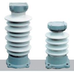
5. The appearance of the product is shown in Figure 1
Figure 1
6. The installation method is shown in Figure 2
Figure 2
6.1 After unpacking, carefully inspect the insulators for any damage during transportation and storage.
6.2 Remove the discharge ring from the insulation cover, place it on the cap of the insulator, firmly fix the insulator and the arc starting plate on the installation bracket, and ensure that the arc starting plate is parallel to the overhead insulated cable.
6.3 Adjust the discharge gap to 145±¡ 5mm as required.
6.4 Handling of Overhead Insulated Cables
6.4.1 At the fixed overhead insulated cable, use a knife to strip the insulation layer of the cable by 100-120mm, as shown in Figure 3.
Figure 3
6.4.2 Tighten the junction between the insulation layer and the bare wire with waterproof insulation tape, as shown in Figure 4.
Figure 4
6.4.3 Wrap 1-2 layers of aluminum tape with a thickness of 1mm and a width of 10mm around the bare wire (2 layers for wires with a cross-sectional area of less than or equal to 70mm2, and 1 layer for wires with a cross-sectional area of less than or equal to 120mm2), as shown in Figure 5.
Figure 5
6.5 Place the processed cable in the groove of the flange on the insulator, rotate the pressure plate horizontally to the installation position, and fix the cable on the insulator with a nut.
6.6 Use a special insulation cover to secure the cable and insulator, fasten the button, and use waterproof insulation tape to wrap and fix the installation foot of the special insulation cover to the cable.
Home|Quality Commitment|Ordering|Payment method|product delivery|support|Disclaimer|Contact Us
Copyright®2011 www.91way.com Copyright.
Phone:+86-21-66770508 +86-13916500500 Fax:+86-21-66108310
Email:91way@163.com Wechat:40606422
沪ICP备2021005791号 ![]() 沪公网安备31010702003255号
沪公网安备31010702003255号