
 Your location:Home → mechanical transmission → Brake | Clutch → electromagnetic brake → SDZ3 series electromagnetic power-off brake
 |
Product name: | SDZ3 series electromagnetic power-off brake | |||||
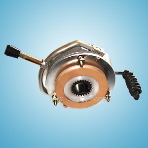
| specification: |   Zoom in on the image Zoom in on the image |
||||||
| Category: | mechanical transmission -- electromagnetic brake | ||||||
| |
Price: | factory price | |||||
| Brand: | Shanghai | ||||||
| Place of Origin: | China | ||||||
| |
Available Quantity: | batch | |||||
| delivery cycle: | Spot goods (or inquire by telephone) | ||||||
 |
|
||||||
The SDZ3 series electromagnetic power-off brake is a type of brake that uses energized electromagnetic attraction and de energized friction braking. A new type of YEJ series electromagnetic braking three-phase asynchronous motor is mainly generated in conjunction with Y series motors. Widely used in metallurgy, construction, chemical, food, machine tools, packaging and other machinery to achieve fast parking and accurate positioning, and can be used in situations such as safe (emergency) braking during power outages.
2、 Characteristics
This type of brake has the advantages of compact structure, easy installation, wide applicability, low noise, high working frequency, sensitive action, and reliable braking. It is an ideal automation actuator in industrial modernization.
3、 Working principle and installation maintenance
The electromagnetic power-off brake mainly consists of the excitation part (yoke 1, coil 2, spring 3, armature 4), brake disc 8, spline 9 sets and other main components. The excitation part is installed on the machine base by installing screw 7. After adjusting the air gap to the specified value δ by turning the installation screw 7, reverse the hollow bolt 6 and tighten the excitation part. Huajian set 9 is connected to the transmission shaft through a key; Brake disc 8 and Huajian sleeve 9 are engaged through splines. When coil 2 is powered off, under the action of spring 3, friction is generated between brake disc 8, armature 4, and machine base end face 10, which is transmitted to the drive shaft through spline sleeve 9 to brake the shaft. When coil 2 is energized, under the action of electromagnetic force, armature 4 is attracted towards magnetic yoke 1, causing brake disc 8 to release and the transmission shaft brake to be released. When there is a power outage during equipment maintenance, the manual release mechanism 5 can be pulled axially to release the brake
Before installation, the friction pair surface should be cleaned of oil stains and debris.
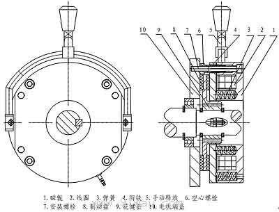
4、 Technical Parameters and Installation Dimension Table (Attached Figures 1 and 2)
|
Project/Model |
SDZ3-04 |
SDZ3-08 |
SDZ3-15 |
SDZ3-30 |
SDZ3-40 |
SDZ3-80 |
SDZ3-150 |
|
Matching motor base number |
seventy-one |
eighty |
ninety |
one hundred |
one hundred and twelve |
one hundred and thirty-two |
one hundred and sixty |
|
Rated braking torque Me (N • m) |
four |
seven point five |
fifteen |
thirty |
forty |
seventy-five |
one hundred and fifty |
|
Rated voltage DC (V) |
ninety-nine |
one hundred and seventy | |||||
|
Rated power P20 ℃ (W) |
thirty |
forty |
fifty |
sixty-five |
seventy |
ninety-five |
one hundred and ten |
|
Braking time (ms) |
one hundred and eighty |
two hundred |
two hundred and fifty |
three hundred and fifty | |||
|
Maximum working air gap (mm) |
zero point five |
one |
one point two | ||||
|
Maximum allowable relative speed (rpm) |
three thousand | ||||||
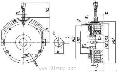
|
model
Size |
D1 |
D2 |
D3 |
D4 |
L |
L1 |
L2 |
L3 |
L4 |
H1 |
H2 |
M |
d |
φ |
h |
b |
δ |
|
SDZ3-04 |
sixty |
thirty-nine |
seventy-two |
eighty-six |
thirty-eight |
eighteen |
two |
seven |
twenty-four |
fifty-two point five |
forty |
3-M4 |
eight |
fifteen |
seventeen point three |
five |
zero point two |
|
SDZ3-08 |
seventy-seven |
fifty-three |
ninety |
one hundred and three |
forty-four |
twenty |
three |
nine |
twenty-four |
sixty |
forty-five point five |
3-M5 |
ten |
twenty |
twenty-two point eight |
six |
zero point three |
|
SDZ3-15 |
ninety-six |
sixty-five |
one hundred and twelve |
one hundred and twenty-seven |
fifty-four point five |
twenty |
three point five |
ten |
twenty-eight point five |
seventy-eight |
sixty-seven |
3-M6 |
ten |
twenty |
twenty-two point eight |
six |
zero point four |
|
SDZ3-30 |
one hundred and sixteen |
eighty |
one hundred and thirty-two |
one hundred and forty-seven |
fifty-six |
twenty-five |
three point five |
twelve |
twenty-eight point five |
ninety |
sixty-seven |
3-M6 |
ten |
twenty-five |
twenty-eight point four |
eight |
zero point four |
|
SDZ3-40 |
one hundred and twenty-four |
eighty |
one hundred and forty-five |
one hundred and sixty-six |
fifty-seven point five |
thirty |
three point five |
twelve |
thirty-three |
one hundred |
sixty-seven |
3-M8 |
ten |
thirty |
thirty-three point three |
eight |
zero point five |
|
SDZ3-80 |
one hundred and fifty |
one hundred and four |
one hundred and seventy |
one hundred and eighty-eight point five |
sixty-eight |
thirty |
three point five |
fourteen |
thirty-nine |
one hundred and thirteen |
sixty-seven |
3-M8 |
ten |
thirty-five |
thirty-eight point three |
ten |
zero point five |
|
SDZ3-150 |
one hundred and seventy-four |
one hundred and twenty |
one hundred and ninety-six |
two hundred and twenty-two |
eighty-one |
thirty-five |
four |
fifteen |
fifty-seven |
one hundred and thirty-two |
one hundred and forty-eight |
6-M8 |
twelve |
forty |
forty-three point three |
twelve |
zero point six |
5、 Precautions
1. Friction plates are vulnerable parts. After wear and tear, the air gap increases. When the maximum allowable air gap of the brake is exceeded, it should be readjusted, otherwise it will affect normal operation and even damage the brake and motor.
2. When operating and braking frequently, it is necessary to regularly check whether the fasteners are loose. If they are loose, they should be readjusted and tightened before use.
3. When the brake is installed on the motor, if the motor has difficulty starting or produces noise, the brake should be checked and adjusted according to Article 3 of this manual.
6、 Control circuit
The working voltage of the brake coil is usually two types: DC 99V and 170V. Our factory has ZL and ZL1 rectifier power supplies specially designed for brake systems, with input and output protection circuits, small size, reliable operation, and overall sealing. They can be directly installed in the junction box of the motor. The wiring method is detailed in the ZL rectifier power supply wiring diagram.
 Related Products:
 TQWZ3 series electric forklift electromagneti.. DZD5-1000 type electromagnetic brake DZD5-320 type electromagnetic brake DZD5-160 type electromagnetic brake DZD5-80 type electromagnetic brake DZD5-40 type electromagnetic brake DZD5-20 type electromagnetic brake DZD5-10 type electromagnetic brake DZD5-5 type electromagnetic brake YHDE Electromagnetic brake multi speed three-.. Related articles:
 speed reducer
  conveyor elevator gearbox divider backstop Brake | Clutch Brake rectifier electromagnetic brake
  Magnetic particle brake eddy current brake Hydraulic thruster Hydraulic brake system electromagnetic clutch Magnetic Particle Clutch Combination clutch Centrifugal clutch overrunning clutch Cam clutch one-way clutch hydraulic clutch Pneumatic brake pneumatic clutch hydraulic coupling buffer shock absorber drive belt drive wheel drive shaft coupling expansion sleeve Chain wheel chain motor bearing motorized roller industrial remote control
 Home|Quality Commitment|Ordering|Payment method|product delivery|support|Disclaimer|Contact Us
Copyright®2011 www.91way.com Copyright.
Phone:+86-21-66770508 +86-13916500500 Fax:+86-21-66108310
Email:91way@163.com Wechat:40606422
沪ICP备2021005791号  沪公网安备31010702003255号

