
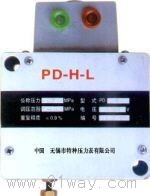
| Product nameŁş | PD-H-L Pressure relay | ||||||
| specificationŁş |  |
||||||
| CategoryŁş | low-voltage electrical apparatus -- pressure relay | ||||||
| PriceŁş | factory price | ||||||
| BrandŁş | |||||||
| Place of OriginŁş | China | ||||||
| Available QuantityŁş | batch | ||||||
| delivery cycleŁş | Spot goods (or inquire by telephone) | ||||||
|
|||||||
| pressure regulation range MPa |
Minimum on/off pressure MPa | Maximum on/off pressure (MPa) | Sensitivity% | Repetition accuracy% | Switch accuracy% | Maximum allowable switching frequency times/minute |
| 0-1.0 | 0.065; zero point zero zero five | 1.0; zero point nine seven | ˇÜ3 | ˇÜ1.2 | <1 | thirty |
| 1-32 | 0.7; 0 | 32;31 | ˇÜ2 | ˇÜ0.5 |
Working temperature: -25 ˇć~70 ˇć
Working medium viscosity: 2.8~380 cst
Protection level: IP54
Working voltage: 24V -; 110V -; 220V~
Switch lifespan: 300000 cycles
Connection thread: M14 ˇÁ 1.5
Instrument execution standard: JB/T6802-1993
External dimensions: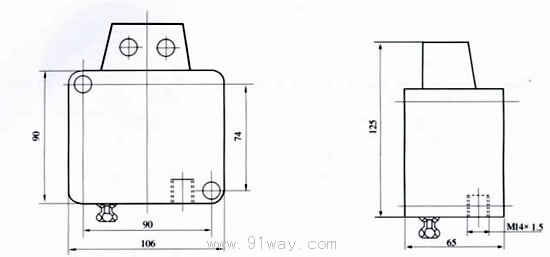
PD-H-L pressure relay wiring diagram: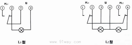
Usage and ordering instructions:
Pressure regulation method:
When adjusting the PD-H-L1 type, the locking nut should be loosened counterclockwise first, and the pressure regulating screw should be rotated clockwise to increase the pressure to the given value displayed on the pressure gauge. Then, the pressure regulating screw should be rotated counterclockwise to activate the micro switch. The indicator light is on, gently tighten the lock nut, repeat fine adjustment until the signal is correct, and lock the lock nut.
The PD-H-L2 pressure regulating method is the same as above. The upper limit regulating screw is located near the label, and the lower limit should be adjusted first, followed by the upper limit.
The working environment should not contain corrosive gases.
Please specify the name, model, voltage regulation range, and working power supply when placing an order.
HomeŁüQuality CommitmentŁüOrderingŁüPayment methodŁüproduct deliveryŁüsupportŁüDisclaimerŁüContact Us
Copyright®2011 www.91way.com Copyright.
PhoneŁş+86-21-66770508 +86-13916500500 FaxŁş+86-21-66108310
Email:91way@163.com Wechat:40606422
»¦ICP±¸2021005791şĹ ![]() »¦ą«Íř°˛±¸31010702003255şĹ
»¦ą«Íř°˛±¸31010702003255şĹ