Purpose:
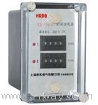
SS-94 time relay is used as a delay control element in the relay protection circuit and automatic control of secondary circuits in power systems. Suitable for situations where high time measurement accuracy is required and the time difference is small.
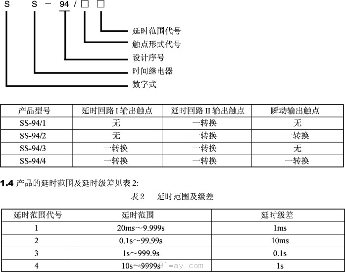
SS-94 time relay model name:
The models of relays and their meanings are as follows:
The number and form of contact points for the product are shown in Table 1:
The delay range and delay level difference of the product are shown in Table 2:
Working Principle:
This relay is a static digital time relay, composed of imported CMOS integrated circuits, using frequency division and counting principles to achieve delay. The standard clock pulse is generated by a quartz crystal oscillator. After applying the rated voltage, the internal instantaneous relay operates and exits, causing the crystal to vibrate and generate clock pulses. After frequency division, the clock pulses are counted by the counter. When the counted pulse number reaches the delay setting, the trigger flips and drives the relay to operate and exit. The schematic diagram of the relay principle is shown in Figure 1
Usage:
4.1 Installation method
Single relay for embedded installation
4.2 Use
a) Pay attention to voltage specifications and positive/negative polarity when using;
b) Should meet the working environment conditions of the product;
4.3 Regular maintenance checks should be conducted on this product, starting with a visual inspection of the printed circuit board for any loose solder joints and broken wires. Next, check if the DC circuit is working properly.
Main technical parameters:
2.3 Structural form and external dimensions
The relay is based on a static principle and is embedded in a plug-in structure. Its external dimensions and opening dimensions are shown in Figure 7 of the universal structural system.
2.4 Relay weight: The weight of the relay shall not exceed 1.1kg
3.1 Rated values: DC 220V, 110V, 48V;
3.2 Delay Setting Range
a) 20ms to 9.999s (with a difference of 1ms);
b) 0.1s to 99.99 seconds (with a difference of 10 ms);
c) 1s-999.9s (with a difference of 0.1s);
d) 10s to 9999s (with a difference of 1s).
3.3 Under reference conditions, the action voltage and return voltage of the relay shall not exceed 70% of the rated voltage, and the return voltage shall not be less than 10% of the rated voltage.
3.4 Delay Consistency Under benchmark conditions, the delay consistency of the relay shall not exceed (0.1% set value+3ms). Delay consistency=maximum value of 5 measurements - minimum value of 5 measurements
Under benchmark conditions, the absolute value of the relay delay setting error shall not exceed (0.1% setting value+3ms). Delay average error=average of 5 measurements - set value
3.6 Return time: The return time should not exceed 25ms.
3.7 Power consumption: At rated voltage, the power consumption of the relay shall not exceed the specified value in Table 2
3.8 Contact Performance
In a DC inductive load circuit with a voltage not exceeding 250V and a current not exceeding 1A (time constant of 5ms ЎА 0.75ms), the contact breaking capacity is 30W.
The conductive terminals of the 3.9 dielectric strength relay connected together should be able to withstand an AC voltage of 2kV (effective value) 50Hz for 1 minute without insulation breakdown or flashover between exposed non charged metal parts or casings.
Working environment conditions
The product should be able to work reliably under the following conditions
a) Environmental temperature: -10 Ўж to+50 Ўж;
b) Atmospheric pressure: 80kPa~110kPa;
c) Relative humidity: The average maximum relative humidity of the wettest month is 90%, and the average minimum temperature of that month is 25 Ўж, with no condensation on the surface. When the highest temperature is 40 Ўж, the average maximum relative temperature does not exceed 50%;
d) In an environment without conductive dust and corrosive gases that can damage metals and insulation;
e) In media without explosion hazard and not filled with dust (such as coal ash, abrasives, sawdust, etc.);
f) Working position: Tilt no more than 5 in any direction. And without severe vibration and impact;
g) The usage location is equipped with rain, snow, wind and sand protection devices and is not filled with water vapor;
h) Places without severe mold presence;
i) Strong external magnetic induction is not allowed in the usage area.
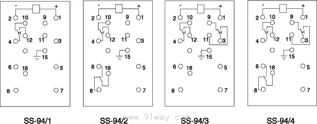
Wiring diagram behind the relay:
Ordering instructions:
a) Product model, name, rated voltage, and structural form (refer to 1.2-1.4);
b) Order quantity;
c) Relay matching: such as base, etc