Purpose:
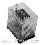
JX-4A, JX-22D, and JX-32D static signal relays are derivative products of the JX series static signal relays produced by our company, suitable for use as signal indicators for relay protection actions in DC operated protection circuits. Especially suitable for signal indication that reflects two consecutive actions.
Features:
2.1 Fast action speed, able to respond promptly to switch on/off status.
2.2 The starting circuit and the reset circuit are independent of each other, and the starting amount can be voltage or current.
2.3 The excitation amount for the start-up and reset circuit can be continuous or pulsed (with a width greater than 50ms).
2.4 Manual and remote electrical reset can meet the requirements of unmanned operation.
2.5 JX-22D and JX-32D models have 5 output contacts, among which two empty contacts and one active contact reflect the first action state, and the other two empty contacts reflect the second action state. The JX-4A model has 4 sets of dynamic contact points, which can hold 3 sets of dynamic contact points, 1 set of instantaneous contact points, or 4 sets of holding contact points.
The indicator lights and contacts on the 2.6 relay panel can reflect two consecutive action states and maintain them, and can be manually or electrically reset in one go.
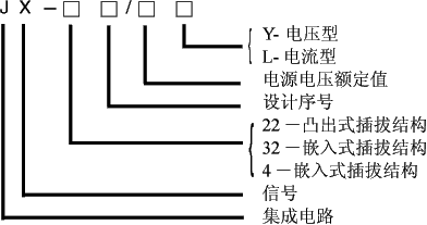
JX-4A, JX-22D, JX-32D type secondary display signal relay model name:
Working Principle:
The relay consists of a starting circuit, a return circuit, a power circuit, a two action discrimination circuit, a momentary relay, a first action relay, and a second action relay. When the starting amount (voltage or current) is added, the instantaneous relay, primary action relay, and secondary action relay are excited by the action coil, and the relay is activated. When the starting quantity is removed, the instantaneous relay returns instantly. Due to the holding function of the circuit itself, only when an external reset voltage is added or the manual reset button is pressed can the primary and secondary action relays be reset to their original state.
The power circuit is used as the working power supply for static relays. When the relay operates continuously twice, the secondary action discrimination circuit causes the signal light to display the indication of primary and secondary actions.
Instructions for using JX-4A, JX-22D, JX-32D type secondary display signal relays:
6.1 When using this relay, a DC auxiliary voltage needs to be applied, which can be taken from the control bus KM+and KM -, or from the signal bus XM+and XM -. When connecting DC voltage, pay attention to whether the rated voltage matches, and pay attention to the polarity of the voltage. If the polarity is connected incorrectly, the relay will not work, but it will not damage the relay.
6.2 During normal operation, manual or electrical reset should be performed to turn off the action indicator light on the panel.
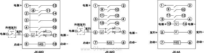
In the 6.3 relay wiring diagram, the power supply (+) and power supply (-) are connected to the auxiliary power supply. The reset (-) terminal of JX-22D and JX-32D relays is connected to the negative terminal of the auxiliary power supply through an external reset contact. The JX-4A relay has no electrical connection between the reset circuit and the auxiliary power supply or starting circuit, so the use of the reset power supply is very flexible. KM+and KM -, XM+and XM - can all be used as reset power supplies, and the reset contacts can be connected to either the reset (+) or reset (-).
If the reset voltage of JX-4A relay is taken from the DC auxiliary power supply, the relay reset (+) can be short circuited to the power supply (+), and the reset (-) can be connected to the auxiliary power supply (-) through an external button or contact. It is also possible to short-circuit the reset (-) to the auxiliary power supply (-), and connect the reset (+) to the auxiliary power supply (+) through an external button or contact.
There are two signal indicator lights on the 6.5 relay panel, which respectively indicate the signal for primary and secondary actions. When the relay is first activated, the primary indicator light will turn on, and the instantaneous relay and the primary action relay will activate. After the excitation amount is removed, the instantaneous relay returns. Due to the circuit's holding function, the primary action relay still maintains its operating state and the primary indicator light remains on. When the relay is not manually or electrically reset and the starting quantity is added for the second time, the instantaneous relay and the secondary action relay will act, and the secondary signal indicator light will light up. After the two indicator lights are lit, they will only turn off when the starting amount is removed and the relay is manually or electrically reset.
Main technical parameters:
5.1 Voltage type relay
a) Rated DC voltage: 48V, 110V, 220V;
b) Auxiliary DC working voltage: 48V, 110V, 220V.
5.1.1 Relay action value: not greater than 70% minimum action.
5.1.2 Relay reset value: not exceeding 80% of the reset voltage.
5.2 Current Relay
a) The operating currents are 0.025A, 0.05A, 0.075A, 0.1A, 0.25A, 0.75A, 1A, and 2A.
b) Auxiliary DC working voltage: 48V, 110V, 220V.
5.2.1 The operating current of the relay shall not exceed 90% of the minimum operating current.
5.2.2 Relay reset value: not exceeding 80% of the reset voltage.
5.3 The action time and return time of the relay shall not exceed 15ms under rated working conditions.
5.4 Power Consumption Relay DC Circuit Power Consumption:
a) 220V: The power consumption before the action is not more than 2W, during the action (when the signal has not disappeared) is not more than 7.5W, and after the action (when holding), the power consumption is not more than 5W;
b) 110V: Before the action, the power consumption should not exceed 1.5W. During the action (when the signal is not lost), the power consumption should not exceed 5W. After the action (when holding), the power consumption should not exceed 3.5W;
c) 48V: The power consumption before the action is not more than 1W, during the action (when the signal has not disappeared) is not more than 3.5W, and after the action (when holding) is not more than 3W;
Power consumption of starting circuit: Voltage type relays shall not exceed 2W, and current type relays shall not exceed 6W at maximum current.
In a DC inductive load circuit with a time constant of 5ms ЎА 0.75ms and a current not exceeding 1A and voltage not exceeding 250V, the contact breaking capacity is 30W. The contact is allowed to close for a long time with a current not exceeding 5A.
5.6 Thermal stability performance voltage type: can withstand 110% of the maximum operating voltage for a long time. Current type: Can withstand 3 times the maximum operating current for 1 minute.
Each circuit of the 5.7 dielectric strength relay should be able to withstand 2kV (effective value) between the exposed non charged metal parts and the shell, and the input circuit should be able to withstand 1kV (effective value) between the contacts, 50Hz AC test voltage, for a duration of 1 minute, and there should be no insulation breakdown or flashover phenomenon.
The insulation resistance between each circuit of the insulation resistance relay and the exposed non charged metal parts, as well as between circuits that are not electrically connected, should not be less than 300M ¦ё when measured with a testing instrument with an open circuit voltage of 500V.
5.9 Working conditions
a) The point of use must not contain explosive media, and the surrounding media must not contain gases or conductive media that corrode or damage metals. It is not allowed to be filled with water vapor or have serious mold presence;
b) Strong vibrations and impacts are not allowed in the usage location;
c) The usage location should have equipment to defend against rain, snow, wind, and sand;
d) The location of use does not allow an external magnetic induction intensity exceeding 1.5mT
5.10 Lifespan
The relay has an electrical lifespan of 10 ^ 4 times and a mechanical lifespan of 10 ^ 5 times under rated operating conditions.
Wiring diagram behind the relay:
Relay external dimensions and opening dimensions:
JX-22D type is shown in Figure 3 of the general structural system;
JX-32D and JX-4A models are shown in Figure 7 of the general structural system.
Ordering instructions:
9.1 Product Model Name
9.2 Rated values of start-up and reset quantities
9.3 Rated value of auxiliary DC voltage
9.4 Order Quantity