Purpose:
JX-3 flash relay is mainly used on various embedded screens. When the protected system fails and the main protection relay is activated, various light signals are controlled through the flash relay.
Relay model name:
Working Principle:
The JX-3 flash relay uses an integrated circuit, resistor, and capacitor to form an RC oscillator, which is controlled by a control circuit to start oscillating. The required oscillation frequency signal is selected by the internal frequency divider of the integrated circuit. Once this signal is amplified, it is output by the relay contacts.
Usage:
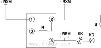
Typical Connection Diagram
Main technical parameters:
4.1 Rated DC auxiliary voltage: 48V, 110V, 220V.
4.2 Flash frequency: 60 times/min.
4.3 Power consumption
The power consumption of the DC voltage circuit (auxiliary excitation quantity) shall not exceed 15W at 220V, 7W at 110V, and 3W at 48V.
4.4 Contact Performance
4.4.1 Contact Capacity:
In a DC circuit with a voltage not exceeding 250V, a current not exceeding 2A, and a time of 40ms, the contact breaking capacity is 30W. In an AC circuit, it is 300VA (coso=0.4 ˇŔ 0.1), and the contact long-term current is 2A.
4.4.2 Relay Contact Form
The relay provides a pair of dynamic contact points.
4.5 Working conditions
a) The usage location does not allow explosive media, and the surrounding media should not contain corrosive metals, gases that damage insulation, or conductive media. It is not allowed to be filled with water vapor or have serious mold presence;
b) Strong vibrations and impacts are not allowed in the usage location;
4.6 Dielectric strength: Each conductive circuit of the relay should be able to withstand 2kV (effective value) between the exposed non charged metal parts and the shell, and the input circuit should be able to withstand 1kV (effective value) between the contacts, 50Hz AC test voltage, for a duration of 1 minute. There should be no insulation breakdown or flashover phenomenon.
4.7 Electrical anti-interference relays shall comply with GB7261 and GB6261 "Electrical anti-interference test for emergency protection devices of static relays".
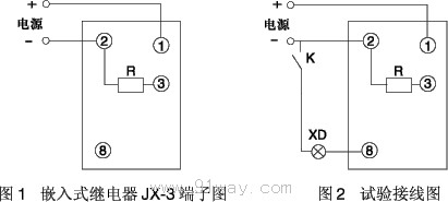
Wiring diagram behind the relay:
Note: The JX-3/A power output terminals are 1 (+), 2 (-), and terminal 8 is connected to an external flash; The JX-3/T power output terminals are 1 (+), 7 (-), and terminal 12 is connected to an external flash.
Relay external dimensions and opening dimensions:
The structure of JX-3/A successor 10 is shown in Figure 1 of the general structural system;
The structure of JX-3/T AJ20 is shown in Figure 3 of the General Row Structure System;
The structure of JX-3 Xuji 30 is shown in Figure 7 of the general structural system.
Ordering instructions:
8.1 Product model, name, auxiliary voltage level, etc.
8.2 Order Quantity.
8.3 Structural Form.