
| Product nameŁş | JC-7 type impulse relay | ||||||
| specificationŁş |  |
||||||
| CategoryŁş | low-voltage electrical apparatus -- Impact relay | ||||||
| PriceŁş | factory price | ||||||
| BrandŁş | |||||||
| Place of OriginŁş | China | ||||||
| Available QuantityŁş | batch | ||||||
| delivery cycleŁş | Spot goods (or inquire by telephone) | ||||||
|
|||||||
Purpose:
JC-7 impact relay is mainly used for various fault centralized alarm and start sound in relay protection and safety automatic device circuits, that is, it is a component that repeatedly operates in the central sound alarm circuit of power stations, substations, and related engineering systems.
Relay model name: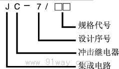
Working Principle:
The JC-7 impact relay consists of a transformer, measurement sampling pulse width detection, trigger memory, automatic reset, delayed action and delayed return, and voltage stabilization circuit. When a certain circuit light sign lights up, current flows through the primary winding of the inverter in the relay, inducing a pulse voltage on the secondary winding of the inverter. This voltage is sent to the action measurement and return measurement circuits respectively. Since the action measurement only has output when the light is on and no output when the light is off, the return measurement does not have output at the same time. Therefore, the action measurement and return measurement will not have output at the same time. Then measure the input pulse width detector to avoid relay misoperation caused by induced voltage in the circuit. The pulse width measurement output is sent to the action delay and return delay circuits, and when it meets the set time, it is output to the outlet relay.
Due to the memory function of the triggering circuit, the pulse is no longer detected after the relay is activated until the light signal is turned off or the external reset causes the relay to return, and then the relay enters the loop state again.
The relay has memory functions for both action and return, with the aim of ensuring interoperability between accident and warning signals in starting the audio system. Additionally, the relay is equipped with an external reset interface.

Usage:
Typical wiring diagram: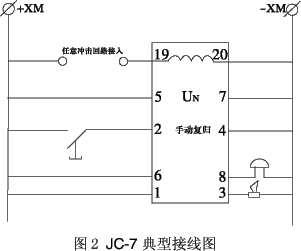
Main technical parameters:
4.1 Rated DC auxiliary voltage: 48V, 110V, 220V.
4.2 Minimum impulse action and reset current: JC-7/11 and JC-7/21 are 0.01A; JC-12 and JC-7/22 are 0.1A.
4.3 Maximum thermal stability current: JC-7/11 and JC-7/21 are 0.8A; JC-12 and JC-7/22 are 4A.
4.4 Rated number of impact circuits: JC-7/11, JC-7/21 shall not be less than 80; JC-12 and JC-7/22 shall not be less than 40.
4.5 Action and return delay setting range: JC-7/21, JC-7/22 delay range is 0-9s, with an error of ˇŔ 10%; JC-7/11 and JC-7/12 have no delay function.
4.6 Power consumption
4.6.1 The power consumption shall not exceed 6W at the rated DC voltage.
4.6.2 Under maximum thermal stability current, the power consumption of the measurement circuit shall not exceed 2W.
4.7 Contact Performance
4.7.1 Contact Capacity: In a DC circuit with a voltage not exceeding 250V, a current not exceeding 5A, and a time constant of 40ms, the contact breaking capacity is 50W. In an AC circuit, it is 500VA (coso=0.4 ˇŔ 0.1), and the contact long-term current is 5A.
4.7.2 Relay Contact Form
JC-7 provides two sets of dynamic contact points.
4.8 Working conditions
a) The usage location does not allow explosive media, and the surrounding media should not contain corrosive metals, gases that damage insulation, or conductive media. It is not allowed to be filled with water vapor or have serious mold presence;
b) Strong vibrations and impacts are not allowed in the usage location;
c) The usage location should have facilities to defend against rain, snow, wind, and sand;
d) The usage location does not allow an external magnetic induction intensity exceeding 1.5mT.
4.9 Dielectric Strength
Each conductive circuit of the relay should be able to withstand an AC test voltage of 2kV (effective value), 50Hz between exposed non charged metal parts and casings, between input circuit contacts, and between different circuits. After a 1-minute test, there should be no insulation breakdown or flashover phenomenon.
4.10 Electrical anti-interference
Relays shall comply with GB7261 and GB6261 "Electrical anti-interference test for emergency protection devices of static relays".
Wiring diagram behind the relay:
Refer to Figure 7 in the general structure.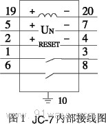
Ordering instructions:
8.1 Product model, name, auxiliary voltage level, etc.
8.2 Order Quantity.
8.3 Relay matching: such as base, etc.
HomeŁüQuality CommitmentŁüOrderingŁüPayment methodŁüproduct deliveryŁüsupportŁüDisclaimerŁüContact Us
Copyright®2011 www.91way.com Copyright.
PhoneŁş+86-21-66770508 +86-13916500500 FaxŁş+86-21-66108310
Email:91way@163.com Wechat:40606422
»¦ICP±¸2021005791şĹ ![]() »¦ą«Íř°˛±¸31010702003255şĹ
»¦ą«Íř°˛±¸31010702003255şĹ