I. Overview
The SH2034D stepper motor driver is a novel subdivision driver developed by absorbing new and high-speed microcontroller technology on the basis of the original driving power supply. This driver adopts high-frequency pulse width modulation technology, which has the advantages of low noise, high efficiency, low temperature rise, flexible setting, beautiful appearance, and good operating characteristics.
2、 Instructions for using the driver
Input power interface: using a set of AC power supply, AC connected to AC 20-40V, 3A or connected to a set of DC power supply DC24-50V, 3A.
Warning: The voltage should not exceed this range, otherwise it may cause malfunction.
Motor interface: For two-phase four wire motors, they can be directly connected to the driver (as shown in Figure 2A).
For a four phase six wire motor, the middle two taps are suspended and not connected, while the remaining four wires are connected to the driver (as shown in Figure 2B).
For a four phase eight wire motor, there are usually two connection methods: parallel connection method: red long connected green short connected to A+, red short connected green long connected to A -, yellow long connected blue short connected to B+, yellow short connected blue long connected to B - (as shown in Figure 2C). Series connection method: red long connected to A+, red short connected green short suspended, green long connected A -, yellow long connected B+, yellow short connected blue short suspended, blue long connected B - (as shown in Figure 2D).
Attention: The suspended joint should be handled properly, otherwise it may cause malfunction (As shown in Figure 2)
Warning: Do not connect the motor wires incorrectly, otherwise it may damage the drive. Red long and green long, as well as red short and green short, cannot be short circuited at the same time.
Figure 2
Input signal interface:
The interface circuit inside the SH2034D stepper motor driver adopts optocoupler signal isolation, as shown in Figure 3
Table 1
|
signal amplitude |
External current limiting resistor R |
|
5V |
not add |
|
12V |
680Ω |
|
24V |
1.8KΩ |
In the figure, R represents an external current limiting resistor. The connection method is differential connection, with good anti-interference performance.
Common anode connection method: OPTO (common anode) is connected to CP+, DIR+, and FREE+respectively. CP series resistor connected to CP -, DIR series resistor connected to DIR -, FREE series resistor connected to FREE -. (Note: The resistor is not connected at 5V)
Common female connection method: CP series resistor connected to CP+, DIR series resistor connected to DIR+, FREE series resistor connected to FREE+. (Note: The resistor is not connected at 5V) Connect the common cathode terminals to CP -, DIR -, and FREE - respectively.
If VCC is greater than+5V, the CP, DIR, and FREE terminals used are respectively connected in series with current limiting resistors R to ensure that 8-15mA of driving current is provided to the internal optocoupler, as shown in Table 1 above
DIR: Direction level signal input terminal, high and low level control motor forward/reverse. The change in signal level should be staggered by more than 2.5us from the falling edge of the CP pulse.
FREE: Offline signal (low level valid). When this input control terminal is low, the motor excitation current is turned off and the motor is in an offline free state.
CP: Step pulse signal input, effective falling edge, maximum response frequency not less than 200KHZ, signal level stabilization time not less than 2.5us.
Warning: The input signal must use sufficient current Generally speaking, TTL and CMOS signals cannot be directly driven, let alone directly driven by pins such as microcontrollers. Otherwise, the system cannot work reliably.
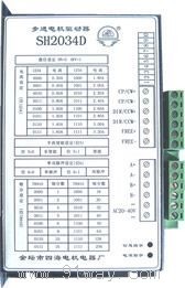
Phase current and fine fraction setting:
The SH2034D subdivision driver uses a toggle switch to set the phase current and subdivision number, where toggle 5 is half current enable (ON indicates non enable, OFF indicates enable), and toggle 6 is single double pulse setting (ON indicates single pulse, OFF indicates double pulse). The specific settings are shown in Table 2 and Table 3. The step angle of the motor after driver subdivision setting is equal to the step angle of the motor divided by the subdivision number. For example, if the subdivision score is set to 18 and a two-phase motor is driven at 0.9 °/1.8 °, the subdivision step angle is 1.8 °/18=0.1 °.
Note: toggle switch ON=0, OFF=1
|
Phase current setting (bits 1, 2, 3, 4) |
|
1 2 3 4 |
phase current |
1 2 3 4 |
phase current |
|
0 0 0 0 |
0.2A |
1 0 0 0 |
1.8A |
|
0 0 0 1 |
0.4A |
1 0 0 1 |
2.0A |
|
0 0 1 0 |
0.6A |
1 0 1 0 |
2.2A |
|
0 0 1 1 |
0.8A |
1 0 1 1 |
2.4A |
|
0 1 0 0 |
1.0A |
1 1 0 0 |
2.6A |
|
0 1 0 1 |
1.2A |
1 1 0 1 |
2.8A |
|
0 1 1 0 |
1.4A |
1 1 1 0 |
3.0A |
|
0 1 1 1 |
1.6A |
1 1 1 1 |
3.2A |
Table 2
|
Detail score setting (bits 7, 8, 9, 10) |
|
7 8 9 10 |
Detail score |
7 8 9 10 |
Detail score |
|
0 0 0 0 |
one |
1 0 0 0 |
eighteen |
|
0 0 0 1 |
two |
1 0 0 1 |
twenty |
|
0 0 1 0 |
four |
1 0 1 0 |
thirty-two |
|
0 0 1 1 |
five |
1 0 1 1 |
forty |
|
0 1 0 0 |
six |
1 1 0 0 |
fifty |
|
0 1 0 1 |
eight |
1 1 0 1 |
sixty-four |
|
0 1 1 0 |
ten |
1 1 1 0 |
one hundred and twenty-eight |
|
0 1 1 1 |
sixteen |
1 1 1 1 |
two hundred and fifty-six |
Table 3
Wiring instructions:
|
CP+: connected to the positive terminal of the pulse |
AC: Connected to 20-40V AC power |
|
CP -: Connected to the negative terminal of the pulse |
A+: Connected to motor A+wire package |
|
DIR+: Connect to the positive end of the direction |
A -: Connected to motor A - Wire package |
|
DIR -: Connect to the negative terminal of the direction |
B+: Connected to motor B+wire package |
|
FREE+: Connect to offline positive terminal |
B -: Connected to motor B - Wire package |
|
FREE -: Connect to offline negative terminal |
|
Note: Information indication: Pulse indication. Power indicator: Power supply is normal
3、 SH2034D stepper motor driver appearance and installation dimensions
The drive adopts a shell structure with a heat sink, and attention should be paid to the heat dissipation of the drive during installation. (Unit: mm)
4、 Common signal indications
|
phenomenon |
reason |
solution |
|
The signal indicator light is flashing red
(Overcurrent) |
1. The motor wire is short circuited
2. The motor has malfunctioned
3. Other reasons |
1. Check the motor wires to eliminate short circuits
2. Replace the motor
3. Send it back for inspection |
The signal indicator light flashes alternately in red and orange
(Overvoltage) |
External voltage exceeds the driver
Working limit voltage |
1. Reduce external voltage |
|
The signal indicator light is red and constantly on
(Under voltage) |
The power supply voltage is too low |
1. Increase the voltage |
The signal indicator light flashes alternately in red and green
(Over temperature) |
The driver temperature exceeds the normal operating temperature |
1. Increase the heat dissipation area of the drive or replace the fan |
| The power indicator light is red and constantly on |
Fuse damaged |
Replace the fuse (same specification) |