Purpose:
JY-2 type DC high and low voltage relay is a DC voltage automatic adjustment test component, which can be used in conjunction with DC, nickel barrier battery screens, etc.
Relay model name:
Note: Structure code "T" refers to the protruding plug-in structure (i.e. 20 structure), structure code "Q" refers to the embedded plug-in structure (i.e. 30 structure), and if the structure code is not written, it defaults to the protruding structure (i.e. 10 structure).

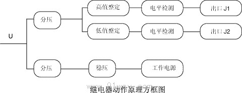
Working Principle:
Under normal circumstances, if the output voltage of the high-value setting circuit is less than the threshold voltage, relay J1 will not operate and the indicator light will not light up. If the output voltage of the low value setting circuit is not greater than the threshold voltage, relay J2 will operate and the dynamic breaking contact will disconnect, and the indicator light will not light up.
When the monitored output voltage changes beyond the setting range of the relay (too high or too low), the dynamic closing (high value) or dynamic breaking (low value) contact of the relay connects the control circuit and sends a signal, that is, the output voltage of the high-value setting circuit is greater than the threshold voltage, the dynamic closing contact closes, the indicator light is on, and the output voltage of the low value setting circuit is not less than the threshold voltage, the dynamic breaking contact closes, and the indicator light is on.
Usage:
The high and low values of the relay can be set separately through the dial switch on the panel. According to the setting formula on the panel, they can be adjusted within the specified setting range of the relay (with an adjustment amplitude of not less than 1V). The dial switch corresponds to the ten and one positions in the setting formula.
Main technical parameters of JY-2 DC high and low voltage relay:
5.1 Rated DC voltage: 110V, 220V.
5.2 Action Setting Range
Rated DC voltage 110V: high value 110V-149V, low value 80V-109V;
Rated DC voltage 220V: high value 220V -260V, low value 190V -220V.
5.3 Action time: When twice the action value, the action time should not exceed 20ms.
5.4 Fixed value error: not greater than ˇŔ 2%
5.5 Return coefficient: The high value is not less than 0.97, and the low value is not greater than 1.02.
5.6 Power consumption: At rated voltage, the power consumption of the relay shall not exceed 6W.
5.7 Contact Performance
When the time constant is 5ms for an inductive load, the breaking capacity of the relay contacts is not greater than 2A for AC voltage of 250V, and not greater than 5A for DC voltage of 24V.
5.8 Working conditions
a) Atmospheric pressure ranging from 80kPa to 106kPa;
b) Environmental temperature -10 ˇć -+50 ˇć
c) The relative humidity of the air shall not exceed 90% (monthly average minimum temperature of 20 ˇć);
d) Strong external magnetic induction intensity is not allowed in the place of use;
e) The place of use does not allow conductive dust or corrosive gases that damage metals and insulation;
f) The place of use does not allow explosive hazards or media filled with dust;
g) The place of use does not allow the presence of severe mold;
h) Strong vibrations and impacts are not allowed in the usage area;
i) The place of use should have rain, snow, wind and sand protection devices and not be filled with water vapor.
5.9 Insulation resistance
The insulation resistance between the relay housing and each terminal, as well as between electrically unrelated circuits, shall not be less than 300M ¦¸.
5.10 Dielectric Strength
The insulation strength between the relay housing and each terminal, as well as between electrically unrelated circuits, should be able to withstand an AC voltage of 2kV, 50Hz for 1 minute without flashover or breakdown. The same group of contacts should be able to withstand 1kV, 50Hz AC voltage for 1 minute without flashover or breakdown.
5.11 Anti interference performance
Compliant with GB7261 and GB6261 "Electrical Interference Test for Static Relays and Protection Devices".
Wiring diagram behind the relay:
The contacts in the picture are in a relay power-off state

Relay external dimensions and opening dimensions:
JY-2A is shown in Figure 1 of the General Structural System;
JY-2A/T is shown in Figure 3 of the General Structural System;
JY-2A/Q is shown in Figure 7 of the General Structural System.
Ordering instructions:
8.1 Relay name and model.
8.2 DC rated voltage (if there are special requirements, please specify separately).
8.3 If the contact form is a special requirement, please specify it separately.
8.4 Order quantity.
8.5 If necessary, the current high and low voltage relay can be modified, with the same setting range and usage method as the DC high and low voltage relay.

