1 Purpose
DY-30 series voltage relay is used in relay protection circuits as an action component for overvoltage protection or low-voltage lockout.
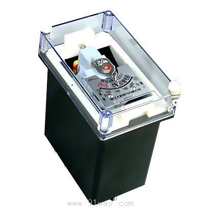
2 Structure and principle
2.1 The relay is electromagnetic and operates instantaneously. The magnetic system has two coils, with the coil heads connected to the base terminals. Users can connect the coils in series or parallel as needed, thus doubling the setting range of the relay.
2.2 The scale value and rated value of the relay nameplate are sufficient for parallel connection of coils (in V units). Rotate the pointer on the dial to change the reaction torque of the balance spring, thereby changing the action value of the relay.
2.3 Relay action: For overvoltage relays, when the voltage rises to or exceeds the set value, the relay will act, closing the contact and disconnecting the contact. When the voltage drops to 0.8 times the set value, the relay returns, the dynamic contact opens, and the dynamic contact closes. For low-voltage relays, when the voltage drops to the set voltage, the relay acts, the dynamic contact opens, and the dynamic contact closes.
2.4 Relays have three structures: A11K, A11H, and A1lQ, as shown in
Appendix II.
The internal wiring diagram of the 2.5 relay is shown in Figure 1.
2.6 Weight of relay: approximately 0.6kg.
The above figure is as follows:
DY-32.36 DY-33.37 DY-34.38
DY-31.35 DY-32ŁŻ60C DY-34ŁŻ60C
Figure 1 Internal wiring diagram of DY-30 series current relay (back view)
Technical data of DY-30 series voltage relay
3.1 The number of contacts is shown in Table 1.
|
model |
Number of contact points |
|
Normally Open |
normally closed |
|
DY-31ˇ˘35 |
one |
|
|
DY-32ˇ˘36 |
one |
one |
|
DY-33ˇ˘37 |
two |
one |
|
DY-34ˇ˘38 |
one |
two |
|
DY-32/60C |
one |
one |
|
DY-34/60C |
one |
two |
3.2 Divided by the range of setting values: The action error of the setting values shall not exceed ˇŔ 6%, and various technical data of the relays are shown in Table 2.
|
model |
Maximum setting
Voltage (V) |
Rated voltage (V) |
Long term allowable voltage (V) |
Voltage setting
Range (V) |
Action voltage (V) |
|
Parallel connection of coils |
Coil series connection |
Parallel connection of coils |
Coil series connection |
Parallel connection of coils |
Coil series connection |
|
DY-32/60C
DY-34/60C |
|
one hundred |
two hundred |
one hundred and ten |
two hundred and twenty |
15~60 |
15~30 |
30~60 |
|
DY-31
DY-32
DY-33
DY-34 |
sixty |
thirty |
sixty |
thirty-five |
seventy |
15~60 |
15~30 |
30~60 |
|
two hundred |
one hundred |
two hundred |
one hundred and ten |
two hundred and twenty |
50~200 |
50~100 |
100~200 |
|
four hundred |
two hundred |
four hundred |
two hundred and twenty |
four hundred and forty |
100~400 |
100~200 |
200~400 |
|
DY-35
DY-36
DY-37
DY-38 |
forty-eight |
thirty |
sixty |
thirty-five |
seventy |
12~48 |
12~24 |
24~48 |
|
one hundred and sixty |
one hundred |
two hundred |
one hundred and ten |
two hundred and twenty |
40~160 |
40~80 |
80~160 |
|
three hundred and twenty |
two hundred |
four hundred |
two hundred and twenty |
four hundred and forty |
80~320 |
80~160 |
160~320 |
Note: DY-32/60C and DY-34/60C specifications are long-term thermal stable (with built-in series capacitors) voltage relays.
3.3 Relay scale phase limit error: not greater than 6%.
3.4 Variation of action values: not greater than 6%.
The return coefficient for voltage relays DY-31, 32, 33, and 34 shall not be less than 0.8; DY-35ˇ˘ The return coefficient of low voltage relays 36, 37, and 38 shall not exceed 1.25.
3.6 Action time
3.6.1 For overvoltage relays
At 1.1 times the action value, the action time should not exceed 0.12s; at 2 times the action value, the action time should not exceed 0.04s.
3.6.2 For low voltage relays
When the working voltage of the relay is 0.5 times the set voltage, the action time shall not exceed 0.15 seconds.
3.7 Overvoltage capability: When the coils are connected in parallel, the voltage should be uniformly raised from zero to 1.05-2.2 times the set voltage at the minimum setting value. Within this range, the relay should not have any vibration that would cause the dynamic contact to malfunction. After this test, the relay should still meet the technical requirements.
3.8 Overvoltage: When applying 1.75 times the set value or higher, the dynamic contact of the relay should close without shaking.
3.9 When there are no external collisions or vibrations. When the working voltage at each setting position of the overvoltage relay (except for the first point) is 0.6 times the setting value, its dynamic breaking contact should reliably close the circuit.
When the working voltage of a low voltage relay is 0.6 times the set voltage or lower, its dynamic breaking contact should close without shaking.
3.11 When there is no external collision or vibration, the working voltage at each setting position of the low-voltage relay should not be less than 1.5 times the setting voltage, and its dynamic contact should reliably close the circuit.
3.12 Under the operating voltage and return voltage; The movable system of the relay should not be stuck in the middle position.
When the relative humidity of the surrounding air is not greater than 85%, the insulation resistance of the relay circuit to the shell (non-conductive metal part on the shell) should not be less than 300M12 when measured with a 500V megohmmeter.
3.14 The insulation of the conductive part of the relay to the shell (non-conductive metal part on the shell) can withstand a test of 50Hz AC voltage 2kV for 1 minute.
3.15 Contact breaking capacity: When the voltage is not greater than 250V and the current is not greater than 2A, the breaking power of the contact is 50W in a DC circuit with inductive load (time constant not greater than 5 ˇÁ 10-3s) and 250VA in an AC circuit.
3.16 Power consumption: At the minimum setting value, the power consumed by the coil of the relay shall not exceed the data in Table 5.
When the temperature of the surrounding medium is+40 ˇć, the relay can operate for a long time under the long-term allowable current and voltage shown in Table 2 and Table 3 without damage to insulation and other electrical components, and the temperature rise of the coil is not greater than 60K.
3.18 Lifespan: The relay has an electrical lifespan of 500 times and a mechanical lifespan of 5000 times.
4. Use and maintenance
4.1 To use a relay, remove the casing, pull out the machine, and check for any damage that may have occurred during transportation, such as contact between the rotor and the magnetic plate, contact between the coils of the balance spring, friction on the rotor shaft, etc. To do so, set the pointer of the relay to the first fixed point, manually rotate the movable system in the direction of the magnetic plate, and then release it. The movable system should return to its original position until it stops, and then make necessary adjustments and settings.
When readjusting the relay, it must be ensured.
4.2.1 The axial movement of the movable system is between 0.15 and 0.3mm.
4.2.2 The air gap between the moving piece and the magnetic pole should ensure that the moving piece and the magnetic plate do not collide under any specified working conditions of the relay.
4.2.3 Relays with dynamic contact points and dynamic contact points shall not have bridge shaped contacts simultaneously make contact with dynamic contact points and dynamic contact points during operation.
4.2.4 When the pointer rotates from the first scale value to the final scale value, the coils of the balance spring do not touch each other.
When the relay is activated, the bridge shaped contact should slide on the centerline of the static contact (tolerance ˇŔ 1mm), and the total air gap between the dynamic and static contacts should not be less than 2mm.
The distance between the static contact point and the limiting plate should not exceed 0.3mm.
4.2.7 When adjusting the action value of the relay, the adjustment of the minimum setting value mainly involves changing the magnitude of the spring reaction force, while the adjustment of the maximum setting value mainly involves changing the air gap between the rotor and the magnetic plate.
4.2.8 Relay shafts and bearings should not be lubricated.
4.2.9 It is not allowed to clean the contacts with sandpaper or other rough materials. It is recommended to use a sharp blade or a clean fine grinding stone to clean the contacts, and then wipe them clean with a clean, soft cloth to avoid touching the contacts with fingers.
5 Ordering Instructions
5.1 Product model and name;
5.2 Maximum setting value (current or voltage)
5.3 Order quantity.